Method for controlling a state machine

a state machine and control technology, applied in the field of control of state machines, can solve problems such as inability to use svf, and achieve the effect of complete flexibility

Active Publication Date: 2016-04-05
ROBERT BOSCH GMBH
View PDF15 Cites 0 Cited by
  • Summary
  • Abstract
  • Description
  • Claims
  • Application Information

AI Technical Summary

Benefits of technology

[0033]One advantage of the presented method is the complete flexibility due to generating arbitrary hardware-related sequences for the JTAG TAP controller of the microcontroller; i.e., firmware does not have to be modified in order to, for example, assist new derivatives of the microcontroller or other manufacturers of the microcontroller with new or different JTAG commands. A tool-assisted generation of the corresponding scripts (ASCII file) is made possible.

Problems solved by technology

A disadvantage of SVF is that the states of the state machine of the TAP controller may run through only in a predetermined manner.
If this is not sufficient, it is not possible to use SVF.

Method used


Image

  • Method for controlling a state machine
  • Method for controlling a state machine
  • Method for controlling a state machine

Examples


Embodiment Construction

[0082]The exemplary embodiments and / or exemplary methods of the present invention are schematically illustrated in the drawings with reference to specific embodiments, and is described in greater detail below with reference to the drawings.

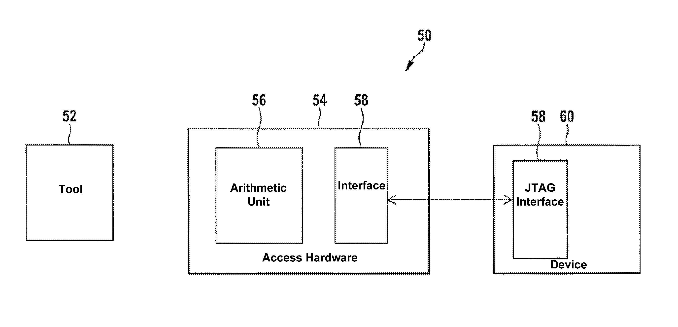
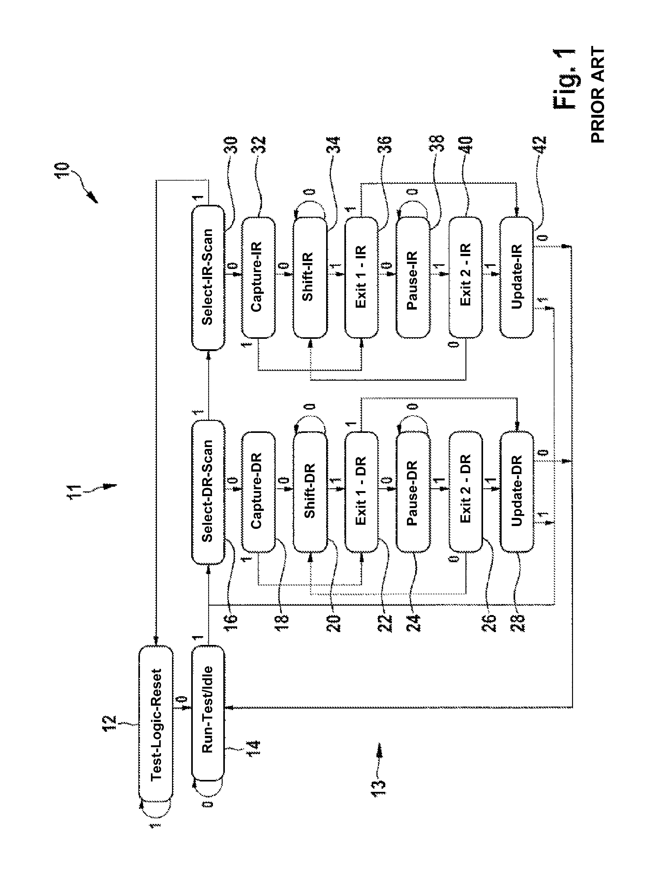
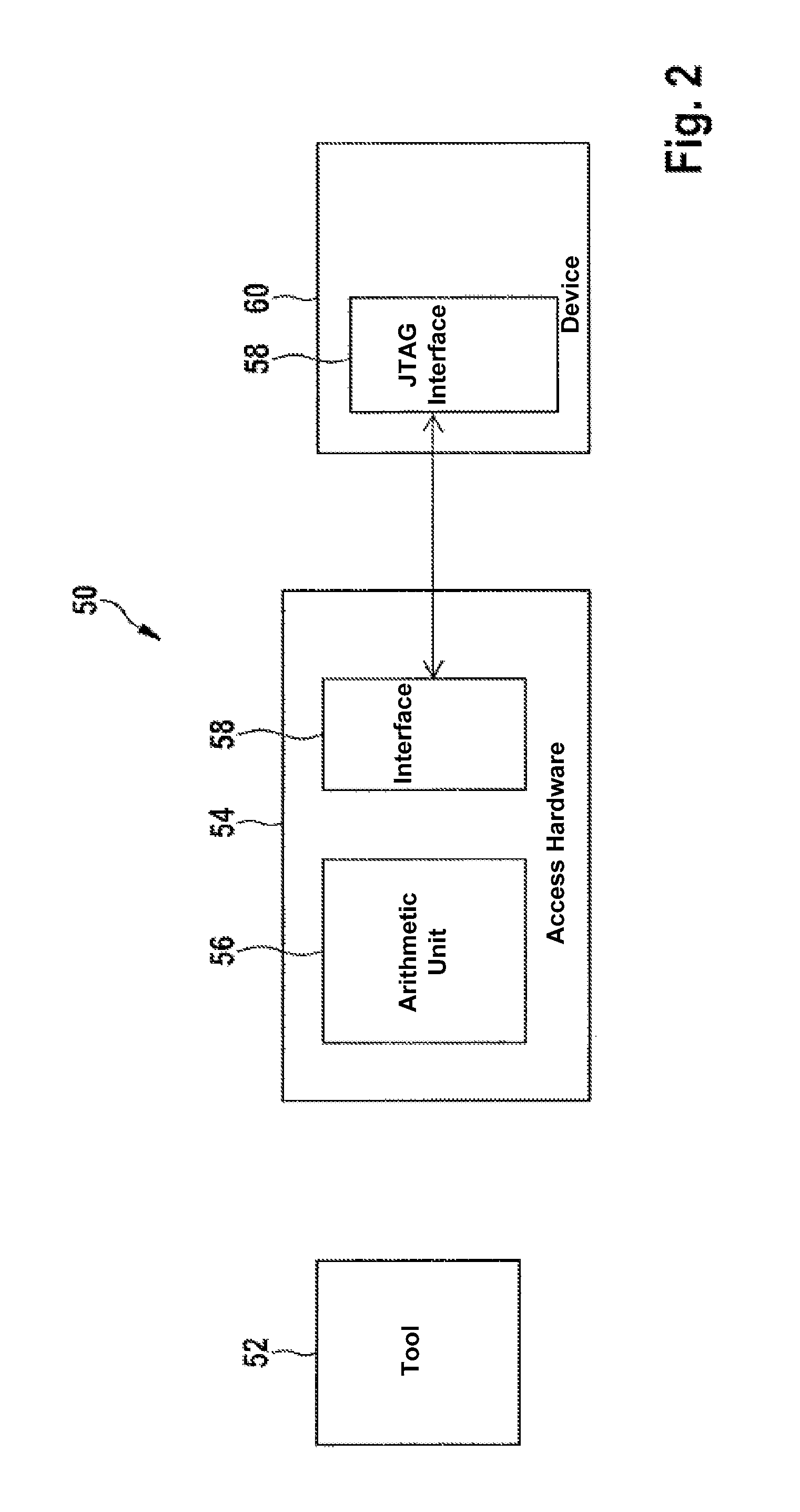
[0083]FIG. 1 illustrates in a state diagram 10 a TAP controller 11 which is used to control a test logic system. This TAP controller 11 represents a state machine 13 whose behavior is described by state diagram 10. The illustration shows a number of states and state transitions. The following states are shown: TEST-LOGIC-RESET 12, RUN-TEST / IDLE 14, SELECT-DR-SCAN 16, CAPTURE-DR 18, SHIFT-DR 20, EXIT1-DR 22, PAUSE-DR 24, EXIT2-DR 26, UPDATE-DR 28, SELECT-IR-SCAN 30, CAPTURE-IR 32, SHIFT-IR 34, EXIT1-IR 36, PAUSE-IR 38, EXIT2-IR 40, UPDATE-IR 42.

[0084]Data input and data output are carried out in the states denoted by reference numerals 20 and 34, respectively. Illustrated state diagram 10 corresponds to the JTAG standard.

[0085]One sequence, i.e., a...


PUM


Abstract

A method and a system for controlling a state machine are described. In the method, a script is used via which each arbitrary path in the state machine. The script is created using a language which includes the “data” command, the “data” command allowing reading and writing of data.

Description

RELATED APPLICATION INFORMATION[0001]The present application claims priority to and the benefit of German patent application no. 10 2012 210 408.9, which was filed in Germany on Jun. 20, 2012, the disclosure of which is incorporated herein by reference.FIELD OF THE INVENTION[0002]The present invention relates to a method for controlling a state machine, and a system for carrying out the method.BACKGROUND INFORMATION[0003]A state machine, also referred to as a finite automaton, represents a model of a system composed of states, state transitions, and actions. The automaton is referred to as “finite” when the quantity of states which the automaton is able to accept is finite.[0004]A state stores the information concerning the past; i.e., the state reflects the changes in the input since the start of the system up to the present point in time. A state transition indicates a change in the state of the automaton, and is described by a logical condition that must be met in order to allow ...

Claims


Application Information

Patent Timeline
Patent Type & Authority Patents(United States)
IPC IPC(8): G06F11/00G06F11/273G01R31/3177G05B19/045G06F9/44
CPCG01R31/3177G05B19/045G06F9/444G06F11/2733G05B2219/23289G06F9/4498
Inventor MAIER, GERTLUSTIG, FRANKHAIBLE, BERNARD
Owner ROBERT BOSCH GMBH
Why Eureka
Try Eureka