Beam combiner for combining two independently scanned illuminating beams of a light scanning microscope

a beam combiner and light scanning microscope technology, applied in the field of beam combiner for combining two illuminating beams of light scanning microscope, can solve problems such as damage to the detector of laser scanning microscop

Active Publication Date: 2017-03-21
CARL ZEISS MICROSCOPY GMBH
View PDF14 Cites 0 Cited by
  • Summary
  • Abstract
  • Description
  • Claims
  • Application Information

AI Technical Summary

Benefits of technology

[0008]In view of the above, the object of the invention is to present a beam combiner for combining two independently scannable illuminating beams of a light scanning microscope that provides complete flexibility with regard to the wavelength of the illuminating beams and does not cause any disruptive losses of intensity in the two illuminating beams.
[0010]The beam combiner has a coupling-in unit having a mirror surface. It is located at the point of intersection of the optical axes of the illuminating beam paths in which the illuminating beams are guided. At least the first beam path is configured in this case in such a way that the first illuminating beam is focused in an intermediate image plane. The mirror surface has an aperture opening at the point of incidence of the optical axis, preferably in the intermediate image plane, so that the first illuminating beam can pass through the mirror without loss. The second illuminating beam is instead deflected at the mirror. The orientation of the mirror surface is selected in such a way that the two beams subsequently propagate as a combined illuminating beam.
[0011]Because the coupling-in unit is arranged in front of a scanner in the second beam path, the second illuminating beam can easily be deflected relative to the first beam path. The result of this deflection is that the point of incidence of the second illuminating beam on the mirror surface depends on the displacement of the scanner for the deflection of the second illuminating beam. As long as this point of incidence does not coincide completely or partially with the aperture opening, the second illuminating beam is also coupled in without loss. There is no coupling-in, or loss-heavy coupling-in, only in the case of scanner positions in which the second illuminating beam falls on the aperture opening. However, this property is exceptionally advantageous for laser scanning microscopy if the second illuminating beam is a beam for sample manipulation. It would then be advantageous to absolutely prevent the sample manipulation beam from hitting the same sample surface as the excitation beam. If such a situation were to occur, damage could occur to the detector of the laser scanning microscope.

Problems solved by technology

If such a situation were to occur, damage could occur to the detector of the laser scanning microscope.

Method used


Image

  • Beam combiner for combining two independently scanned illuminating beams of a light scanning microscope
  • Beam combiner for combining two independently scanned illuminating beams of a light scanning microscope
  • Beam combiner for combining two independently scanned illuminating beams of a light scanning microscope

Examples


Embodiment Construction

[0026]In describing preferred embodiments of the present invention illustrated in the drawings, specific terminology is employed for the sake of clarity. However, the invention is not intended to be limited to the specific terminology so selected, and it is to be understood that each specific element includes all technical equivalents that operate in a similar manner to accomplish a similar purpose.

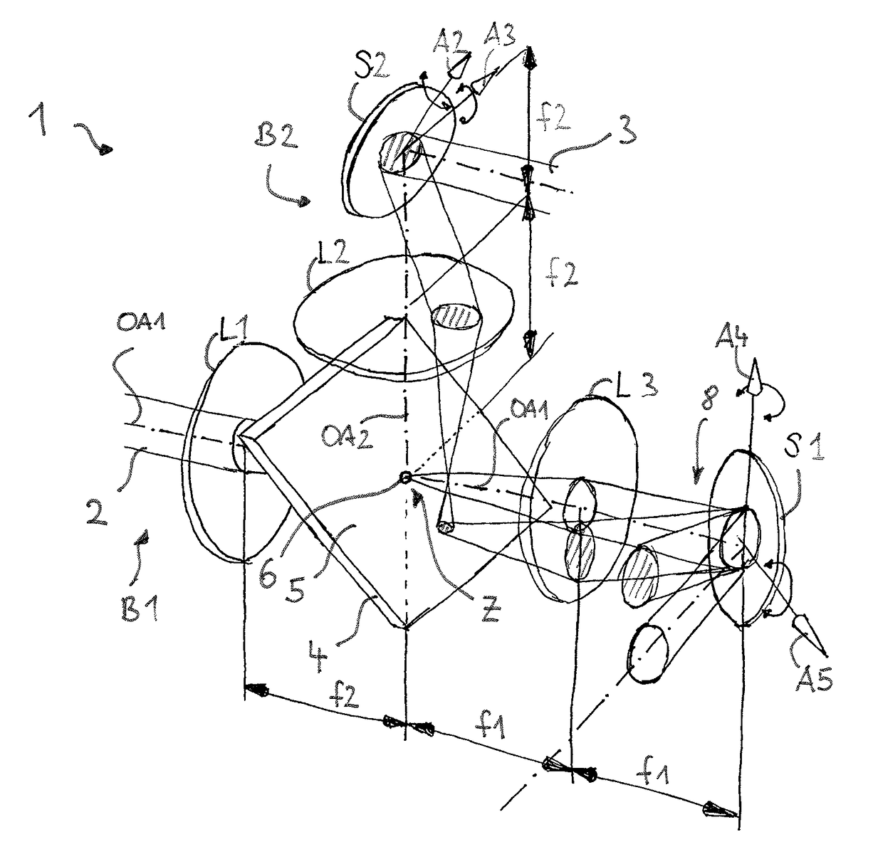
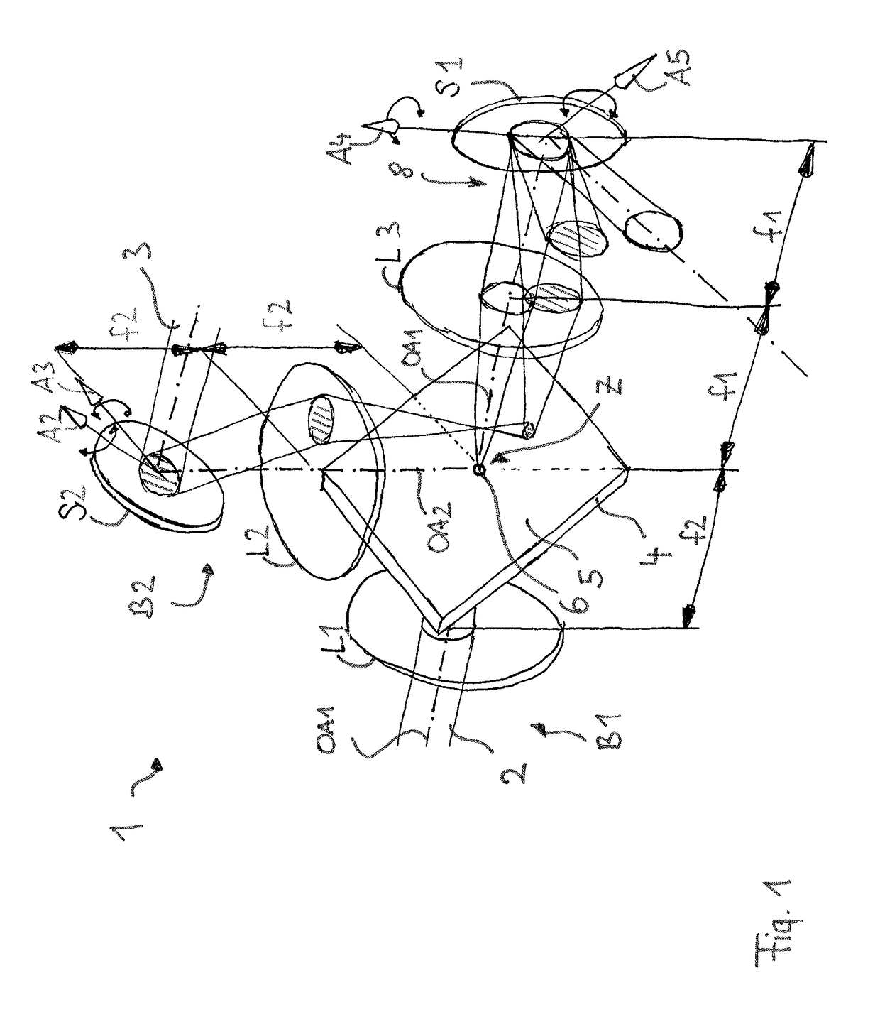
[0027]FIG. 1 diagrammatically shows a beam combiner 1 which is configured for use in a light scanning microscope. The beam combiner 1 combines a first illuminating beam, which may be represented by an excitation beam 2, with a second illuminating beam, which in the described embodiment may be a manipulation beam 3. For clearer distinction, the cross-section of the manipulation beam 3 is cross-hatched in the illustration of FIG. 1. The beam combiner 1 is configured in such a way that the first and second illuminating beams are provided as parallel beam bundles. The excitation beam 2 is gui...


PUM


Abstract

A beam combiner in a light scanning microscope for combining two illuminating beams that can be independently scanned. A first beam path (B1) guides a first illuminating beam (2) along a first optical axis (OA1) and a first optical device (L1) bundles the first beam (2) in an intermediate image plane. A second beam path (B2) guides a second illuminating beam (3) along a second optical axis (OA2) that intersects the first optical axis (OA1) at a point of intersection (Z) lying in or near the intermediate image plane, and a scanner (S2) for deflecting the second illuminating beam (3) and arranged before the point of intersection (Z) of the optical axes (OA1, OA2) in the propagation direction of the second illuminating beam (3). A coupling-in unit (4) is arranged at the point of intersection (Z) of the optical axes (OA1, OA2) and either has a mirror surface (5) having a passage opening (6; 7) at the point of incidence of the first optical axis (OA1), or is transparent except for a mirror element lying at the point of incidence of the first optical axis (OA1), wherein the size of the passage opening (6; 7) or the mirror element corresponds to the cross-section that the first illuminating beam (2) at the point of incidence and thus allows the first illuminating beam to pass or reflects the first illuminating beam, wherein the first and second illuminating beams (2, 3) propagate as a combined illuminating beam (8) after the coupling-in unit (4).

Description

CROSS REFERENCE TO RELATED APPLICATIONS[0001]This application is a continuation of International Application No. PCT / EP2012 / 060879, filed Jun. 8, 2012, which claims priority of German Application No. 10 2011 077 327.4, filed Jun. 9, 2011, both of which are incorporated herein by reference in their entireties.BACKGROUND OF THE INVENTION[0002](1) Field of the Invention[0003]The invention relates to a beam combiner for combining two illuminating beams of a light scanning microscope that can be independently scanned.[0004](2) Description of Related Art Including Information Disclosed Under 37 CFR 1.97 and 1.98[0005]In light scanning microscopy, there is a need to overlay two or more scanned illuminating beams. The overlay of a fluorescence excitation beam with a manipulation beam that manipulates the fluorescence properties of the sample at specific places (e.g., by bleaching the sample) is referenced as an example.[0006]Dichroic beam splitters are known in the art use as for beam combi...

Claims


Application Information

Patent Timeline
Patent Type & Authority Patents(United States)
IPC IPC(8): G02B21/00G02B27/14G02B27/10
CPCG02B21/0048G02B21/0032G02B21/0076G02B27/108G02B27/143
Inventor KRAMPERT, GERHARDSTUTZ, MICHEL
Owner CARL ZEISS MICROSCOPY GMBH
Why Eureka
Try Eureka