Fuel cell stack with compression means

a technology of compression means and fuel cells, applied in the field of fuel cell modules, to achieve the effect of ensuring the thickness ensuring the stability of the sealing material, and ensuring the stability of the fuel cell stack

Pending Publication Date: 2022-04-14
EH GRP ENG SA
View PDF4 Cites 0 Cited by
  • Summary
  • Abstract
  • Description
  • Claims
  • Application Information

AI Technical Summary

Benefits of technology

[0006]The present invention proposes a new solution which overcome this issue regardless of the design of the external compression kit. One of the main advantages of the new invention is that It provides a method with complete flexibility in the assembly that allows accurate adjustment of pressure applied either on the active area or the sealings around the cells before assembly.
[0007]Another advantage is the possibility to tweak the load applied on the active area after assembly.
[0008]Another advantage is that it assists to optimise thickness of the sealing material, which could simplify design of the plate in an assembly.
[0009]Another advantage is that, it guarantees a uniform pressure distribution on the active area especially around the cell edges that are closer to the gas manifolds.

Problems solved by technology

However, key challenge is to have the possibility to apply compression on the active area and also the manifolds independently and to be able to adjust the applied force accurately.

Method used


Image

  • Fuel cell stack with compression means
  • Fuel cell stack with compression means
  • Fuel cell stack with compression means

Examples


Embodiment Construction

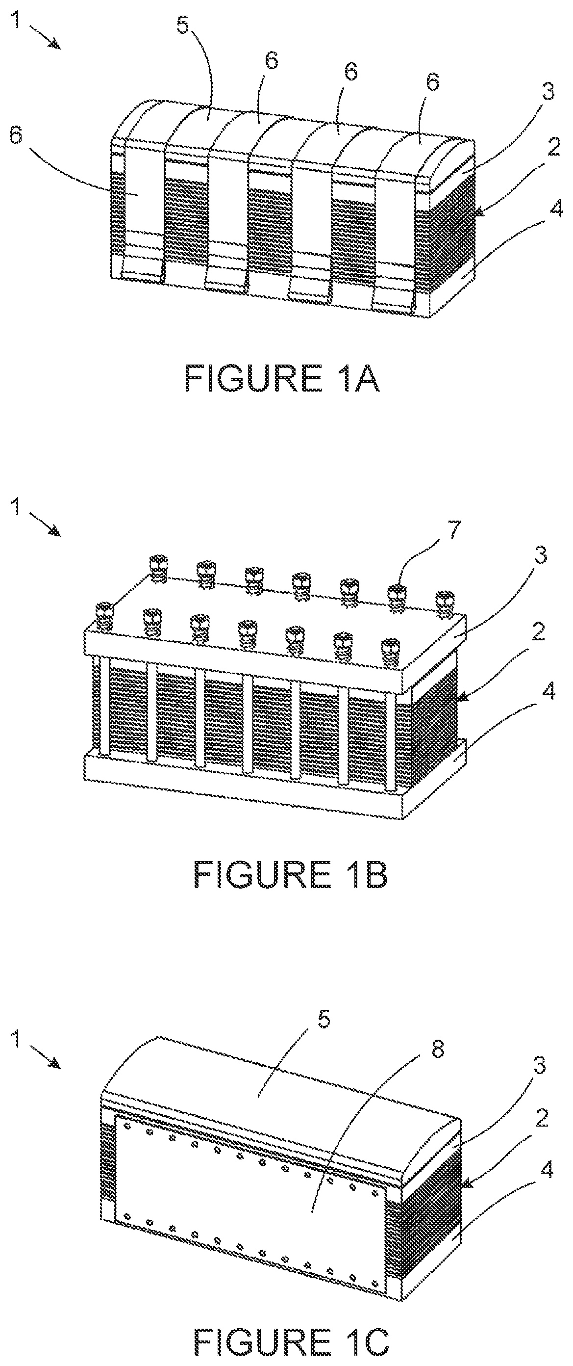
[0045]FIG. 1 represents a conventional and state of the art stack assembly 1 with compression means. The assembly forming a fuel cell comprises several cells 2 assembled on top of each other that are encapsulated with two end plates 3, 4 at the top (plate 3) and the bottom (plate 4) and with a cover 5. As stated above, there are several techniques to keep the assembly in compressed form and in FIG. 1 different solutions are shown

[0046]FIG. 1A compression with belts 6 (ex. US2006093890A1),

[0047]FIG. 1B rods 7 and springs (ex. US2002110722A155) and

[0048]FIG. 1C side-panels 8 (ex. JP2012181996A).

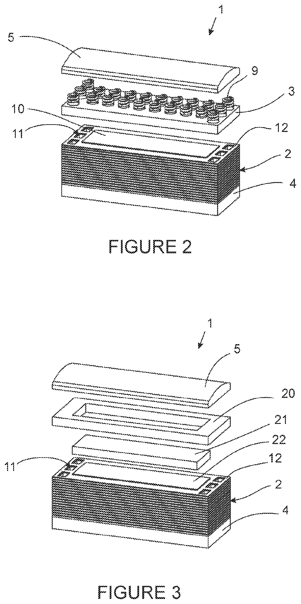
[0049]FIG. 2 shows the stack assembly 1 of FIG. 1 in an uncompressed state and exploded view. The shape and structure of the integrated compression springs 9 for compression can be different based on the design and application of the fuel cell; however, the main principle in assembly is the same. There are several compression springs 9 located between the top end plate 3 and top cover 5 or in c...


PUM

PropertyMeasurementUnit
pressureaaaaaaaaaa
areaaaaaaaaaaa
compression forceaaaaaaaaaa

Abstract

The fuel cell includes several assembled cells with end plates at the top and bottom of the cells that are compressed using an external retention kit. An end plate that is at the top or bottom of the assembly which separates the compression force on the active area and sealant around the cell. The end plates give the freedom and flexibility to adjust compression force on specific areas in the assembly accurately without interfering with other components and the active area.

Description

CORRESPONDING APPLICATION[0001]The present application claims priority to earlier Swiss application NoCH 00146 / 19, filed on Feb. 7, 2019 in the name of EH GROUP Engineering SA, the content of this earlier application being incorporated by reference in its entirety in the present application.BACKGROUND[0002]The present invention relates to a fuel cell module and a method for manufacturing and assembling the same.PRIOR ART AND SUMMARY OF THE INVENTION[0003]There are several patent applications published that introduces a structure or a method by which a multi-layer stack is compressed and kept under load. For example, patent application US2017025701A1 proposed a few metallic frames that encapsulate the stack on the sides in order to keep it compressed during operation. Patent application US2018316039A1 designed a new compression mechanism where wires are wrapped around the stack. There are several other applications such as US2006093890A1, US2008145713A1, US2008311457A1, US2008305380A...

Claims


Application Information

Patent Timeline
Patent Type & Authority Applications(United States)
IPC IPC(8): H01M8/248H01M8/0276H01M8/2483
CPCH01M8/248H01M8/2483H01M8/0276H01M8/0247H01M8/247Y02E60/50
Inventor MATIAN, MARDITCHAINHO, ALEXANDRE
Owner EH GRP ENG SA
Why Eureka
Try Eureka