
Solder handling assembly

a technology of handling assembly and soldering rod, which is applied in the direction of ohmic-resistance heating, manufacturing tools, and soldering apparatus, etc., can solve the problems of damage to the component being soldered or desoldered

Active Publication Date: 2016-04-19
HAKKO CO LTD
View PDF31 Cites 21 Cited by
  • Summary
  • Abstract
  • Description
  • Claims
  • Application Information

AI Technical Summary

Problems solved by technology

However, an unduly high temperature setting can damage the component being soldered or desoldered.

Method used


Image

  • Solder handling assembly
  • Solder handling assembly
  • Solder handling assembly

Examples


Embodiment Construction

[0035]As used herein, the words “operator” and “user” are used interchangeably and refer to a person that is operating or using a subject device.

[0036]As used herein, the phrases “integrally formed”, “integrally provided”, and the like mean that the subject structures are a unitary construct of the same material, and there is no intervening connector that fixes the structures together. For example, a first structure that is integrally formed with a second structure can be the result of injection molding and / or a milling operation.

[0037]As used herein, the phrase “coupled to” means that the subject structures are attached together in such a way that the structures move simultaneously together in one or more directions. For example, a first structure that is coupled to a second structure is attached, either directly or indirectly via an in intervening connector, to the second structure so that the first structure rotates when the second structure is rotated. The first structure may or...


PUM


Abstract

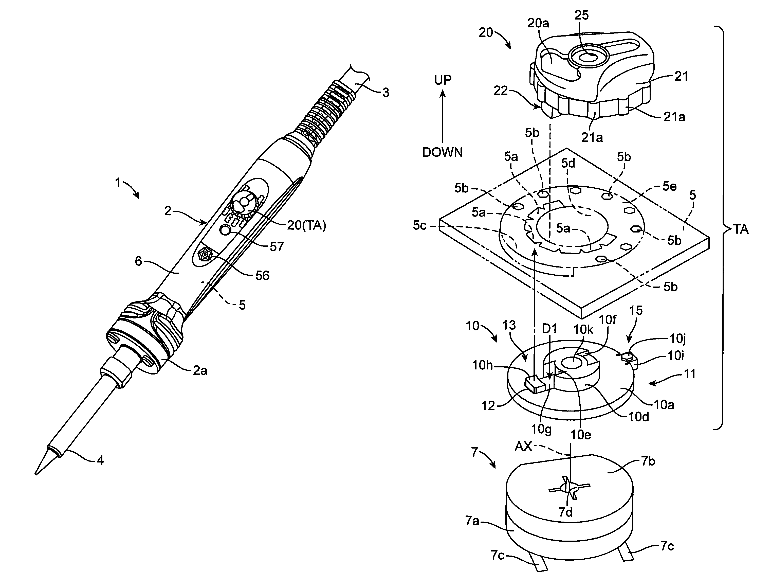
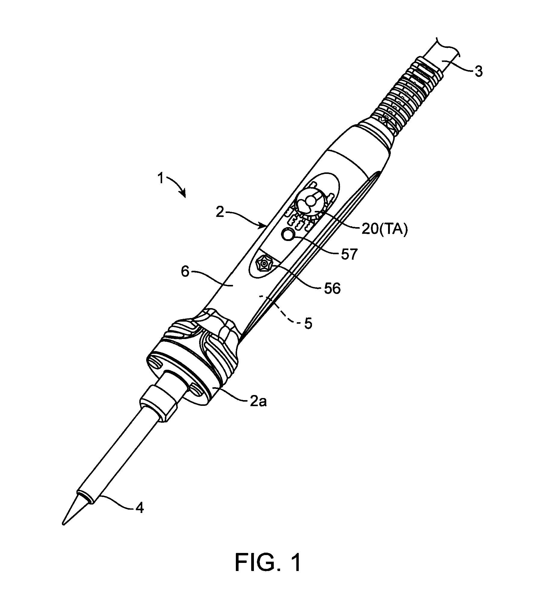
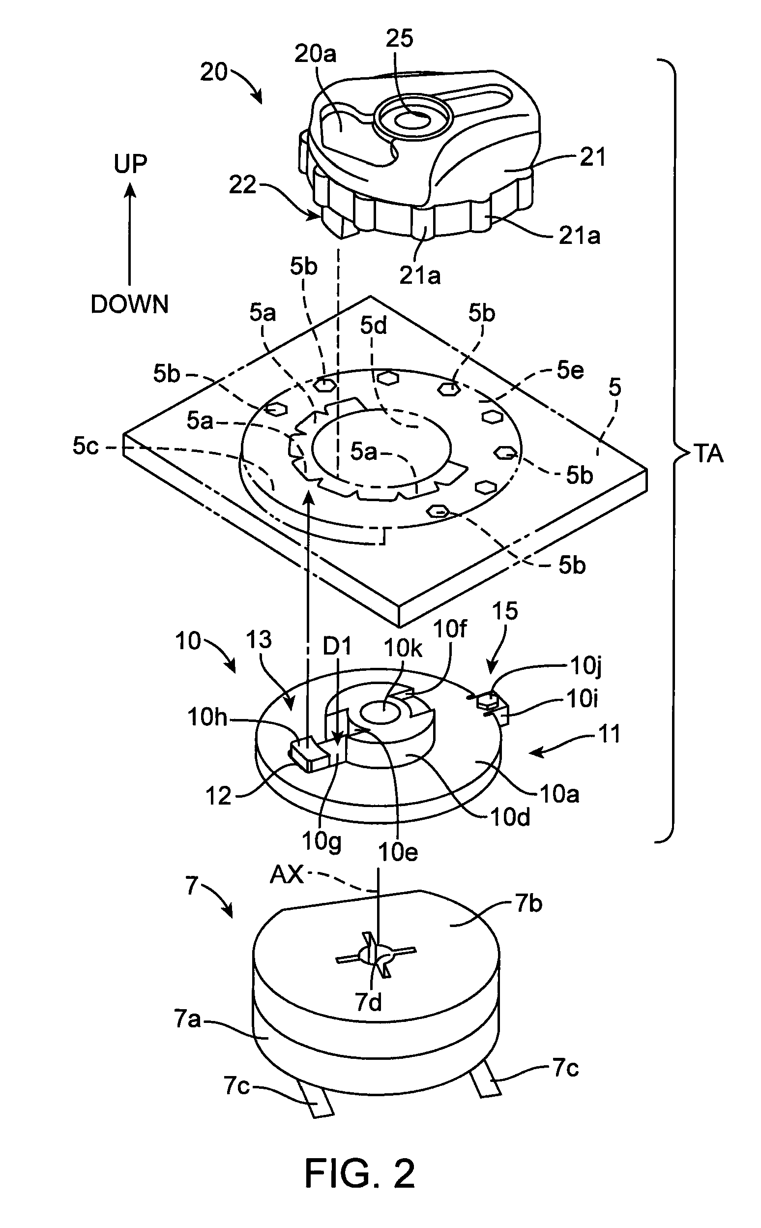
A solder handling assembly comprises a heating portion, a casing, a variable resistor, a connecting member coupled to the variable resistor, and an elastic-resilient member movable from a first state to a second state. The connecting member is rotatable relative to the casing and is configured to adjust a resistor value of the variable resistor when the connecting member is rotated relative to casing. When the elastic-resilient member is in the first state, the connecting member is prevented from rotating relative to the casing. When the elastic-resilient member is in the second state, the connecting member can be rotated relative to the casing.

Description

FIELD OF THE INVENTION[0001]This invention relates generally a solder handling assembly, more particularly, to a solder handling assembly with a temperature adjustment feature.BACKGROUND[0002]Examples of a solder handling assembly include, without limitation, a soldering iron having a tip to melt solder, a desoldering device, and a hot air device. A desoldering device may have a nozzle with a heater inside, and the nozzle is used to melt and remove solder from a work piece. A hot air device melts solder by applying hot air to the solder, and such a device can be used for both soldering and desoldering. These and other devices are referred to herein as solder handling assemblies. The handling of solder, whether to apply or remove solder, is referred to herein as a solder handling operation.[0003]A solder handling operation is typically performed at an appropriate temperature which has been predetermined. The appropriate temperature can depend on several factors, such as the type of s...

Claims


Application Information

Patent Timeline
Patent Type & Authority Patents(United States)
IPC IPC(8): B23K3/00H05B1/02B23K3/03
CPCB23K3/033
Inventor TERAOKA, YOSHITOMO
Owner HAKKO CO LTD
Learn More