Wrist fusion plate

a wrist and fusion plate technology, applied in the field of plates, can solve the problems of improper wrist bone fusion, wrist fracture or treatment, severe pain for patients, etc., and achieve the effect of optimal wrist orientation and optimal wrist orientation

Active Publication Date: 2016-04-26
STRYKER EURO OPERATIONS HLDG LLC
View PDF16 Cites 44 Cited by
  • Summary
  • Abstract
  • Description
  • Claims
  • Application Information

AI Technical Summary

Benefits of technology

[0007]It is therefore one aspect of the invention to provide a wrist fusion plate that can be adaptively used by a surgeon to obtain an optimal wrist orientation. It is a further aspect to provide a method of implanting a wrist fusion plate onto a wrist of a patient, whereby optimal wrist orientation can be achieved.

Problems solved by technology

However, proper alignment of the bones of the wrist can be very difficult, and any misalignment can result in severe pain to the patient, especially when attempting to use the hand, and may also result in improper healing or fusion of fractured or treated bones of the wrist.
Additionally, the intricate network of tendons, muscles, and nerve endings in the wrist joint and the area of the hand can make proper fixation difficult, as the surgeon must be careful not to damage surrounding tissues as much as possible when fixing the wrist plate.
However, known wrist fusion plates have disadvantages in that it is difficult to position and fix the bones of the wrist and hand in an optimal orientation, as the wrist fusion plates typically have a predefined ulnar / radial deviation and a predefined dorsal / palmar flexion.
Therefore, when a patient has an unusual anatomy due to deformation, whether rheumatoid, genetic, or post-traumatic, it can be difficult to obtain an optimal metacarpal orientation with existing wrist fusion plates.

Method used


Image

  • Wrist fusion plate
  • Wrist fusion plate
  • Wrist fusion plate

Examples


Embodiment Construction

[0034]Hereinafter, embodiments of the wrist fusion plate will be described with reference to the accompanying figures. The same reference numerals are used to refer to identical or similar elements. In the following, the term “distal” refers to a direction toward a patient's fingertips, and the term “proximal” refers to a direction toward a patient's radius and ulna.

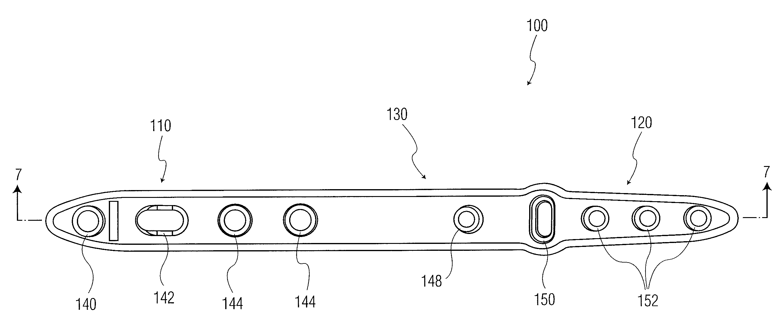
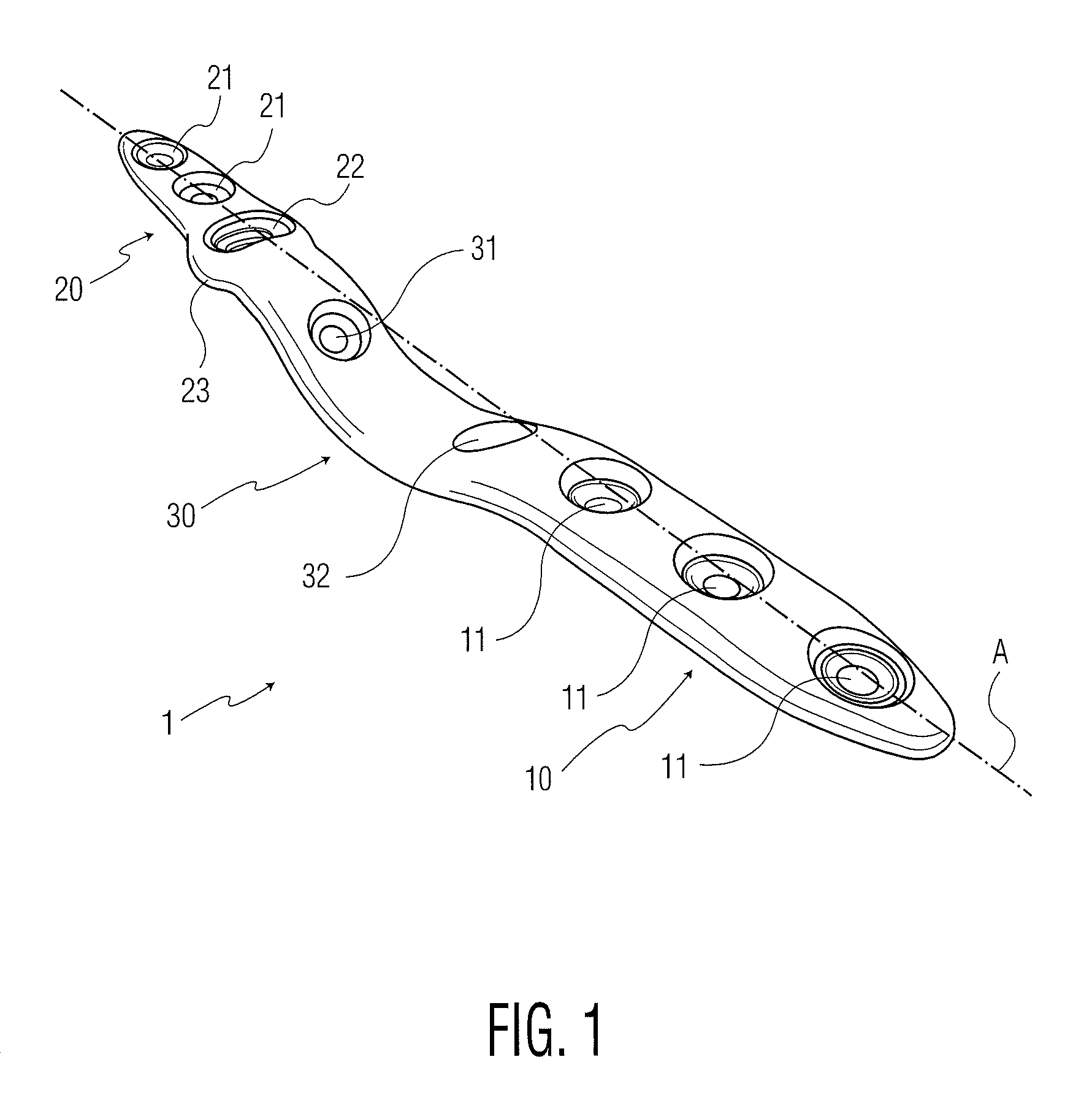
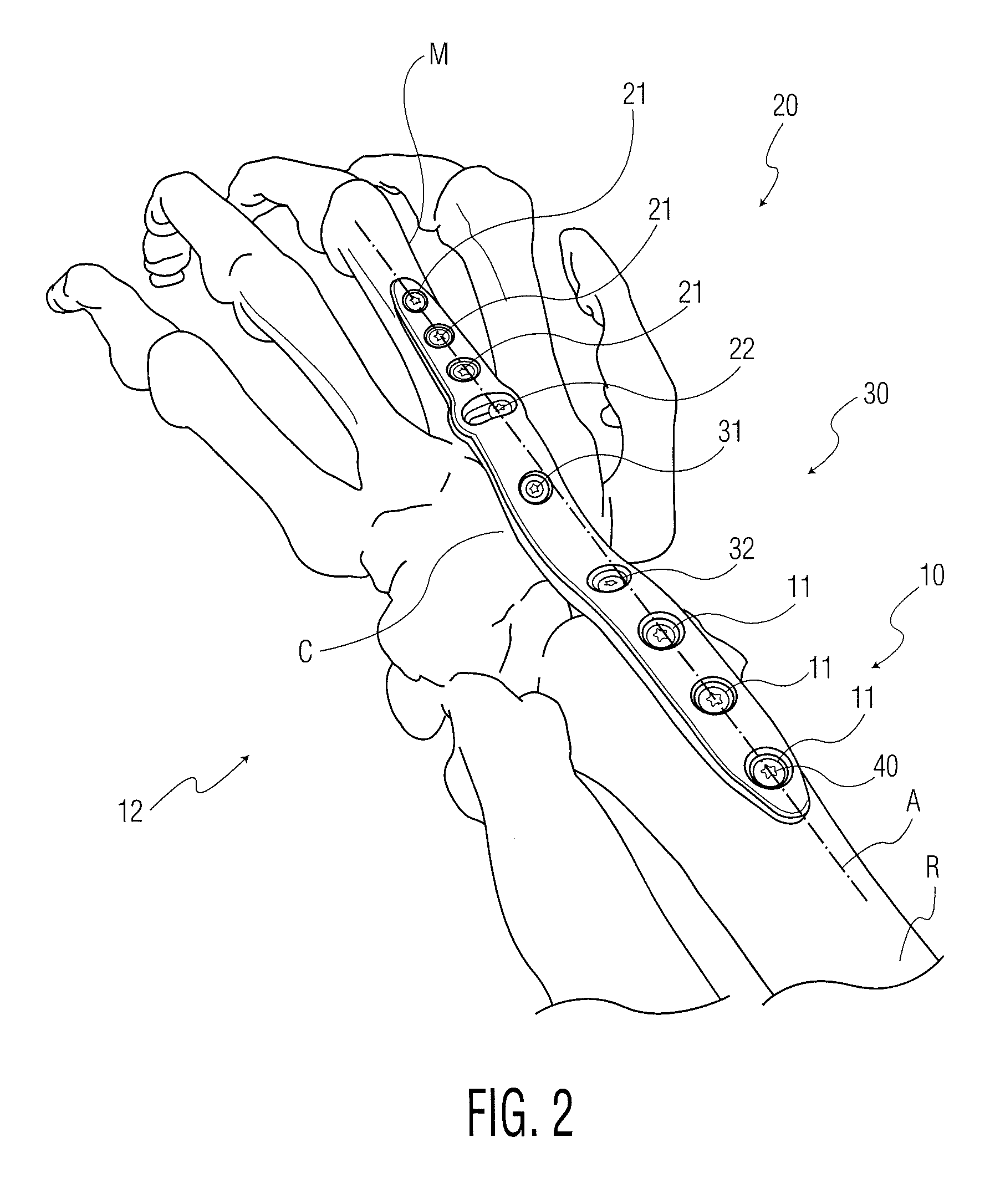
[0035]FIG. 1 shows a perspective view of a first embodiment of the wrist fusion plate 1. The wrist fusion plate 1 comprises a proximal portion 10, a distal portion 20, and a central portion 30. The proximal portion 10 is sized and shaped to be attached to a radius of the patient. The distal portion 20 is sized and shaped to be attached to a metacarpal bone of the patient. Moreover, the central portion 30 is sized and shaped to be attached to at least one carpal bone of the patient's wrist. Specifically, the central portion 30 may be sized and shaped to be attached to a capitate bone of the carpal bones. The distal and pr...


PUM


Abstract

A wrist fusion plate has a proximal portion comprising at least one opening, wherein the proximal portion attaches to the radius by inserting bone screws through the proximal portion opening. A distal plate portion has a plurality of openings and is adapted to be attached to a metacarpal (M) by inserting bone screws through the distal portion attachment openings and into the metacarpal. A central plate portion has at least one attachment opening and is adapted to be attached to a carpal bone by inserting bone screws through the attachment opening. The proximal and distal portions are aligned along a longitudinal axis of the wrist fusion plate. One of the distal portion attachment openings is elongated in a direction perpendicular to the longitudinal axis.

Description

CROSS-REFERENCE TO RELATED APPLICATION[0001]The present application claims the benefit of the filing date of U.S. Provisional Patent Application No. 61 / 579,210 filed Dec. 22, 2011, the disclosure of which is hereby incorporated herein by reference.BACKGROUND OF THE INVENTION[0002]The present disclosure generally relates to a plate for application to a wrist joint for use in an orthopaedic procedure, and, more particularly, to a wrist fusion plate for use in fusing a wrist joint. The wrist fusion plate may be applicable for correction of bone deformation due to arthritis, rheumatoid arthritis, inflammatory diseases such as rheumatic fever or tuberculosis, genetic disorders of the bone, or for setting a wrist fracture.[0003]In the field of treating wrist disorders (e.g., surgical procedures for realigning misaligned or deformed wrist bones), a surgeon implants a wrist plate and attaches one or several bone attachment members into desired locations on the bones of the wrist through the...

Claims


Application Information

Patent Timeline
Patent Type & Authority Patents(United States)
IPC IPC(8): A61B17/80
CPCA61B17/8061
Inventor GREENBERG, JEFFREY A.BLUECHEL, TOBIASHENRY, PHILIPKOZIC, NINA
Owner STRYKER EURO OPERATIONS HLDG LLC
Why Eureka
Try Eureka