Columnar air moving devices, systems and methods

a technology of air moving devices and columns, applied in ventilation systems, heating types, applications, etc., can solve problems such as air temperature stratification, significant increase in heating and air conditioning costs, and air temperature stratification problems

Inactive Publication Date: 2016-05-10
AIRIUS IP HLDG
View PDF295 Cites 42 Cited by
  • Summary
  • Abstract
  • Description
  • Claims
  • Application Information

AI Technical Summary

Benefits of technology

[0012]Therefore, it would be advantageous to not only have an air de-stratification device that is designed to de-stratify the air in a room and reduce pockets of high temperature near the ceiling, but also to have an air de-stratification device that additionally houses a light source member, and through use of heat exchange during the de-stratification process, keeps the light source member as cool as possible.

Problems solved by technology

Air temperature stratification is particularly problematic in large spaces with high ceilings such as warehouses, gymnasiums, offices, auditoriums, hangers, commercial buildings, residences with cathedral ceilings, agricultural buildings, and other structures, and can significantly increase heating and air conditioning costs.
Structures with both low and high ceiling rooms can often have stagnant or dead air, as well, which can further lead to air temperature stratification problems.
Conventional ceiling fans are generally ineffective as an air de-stratification device in relatively high ceiling rooms because the air pushed by conventional ceiling fans is not maintained in a columnar pattern from the ceiling to the floor, and often disperses or diffuses well above the floor.
Such devices, when located away from the walls in an open space in a building, interfere with floor space use and are not aesthetically pleasing.
When confined to locations only along the walls of an open space, such devices may not effectively circulate air near the center of the open space.

Method used


Image

  • Columnar air moving devices, systems and methods
  • Columnar air moving devices, systems and methods
  • Columnar air moving devices, systems and methods

Examples


Embodiment Construction

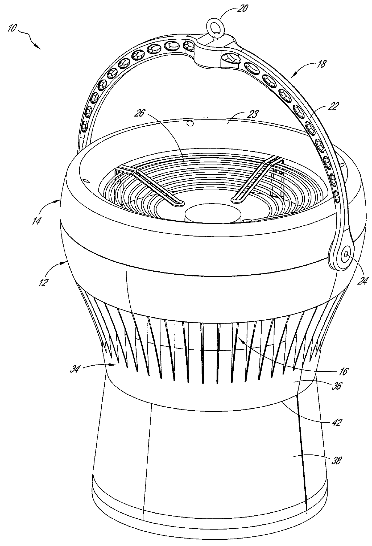
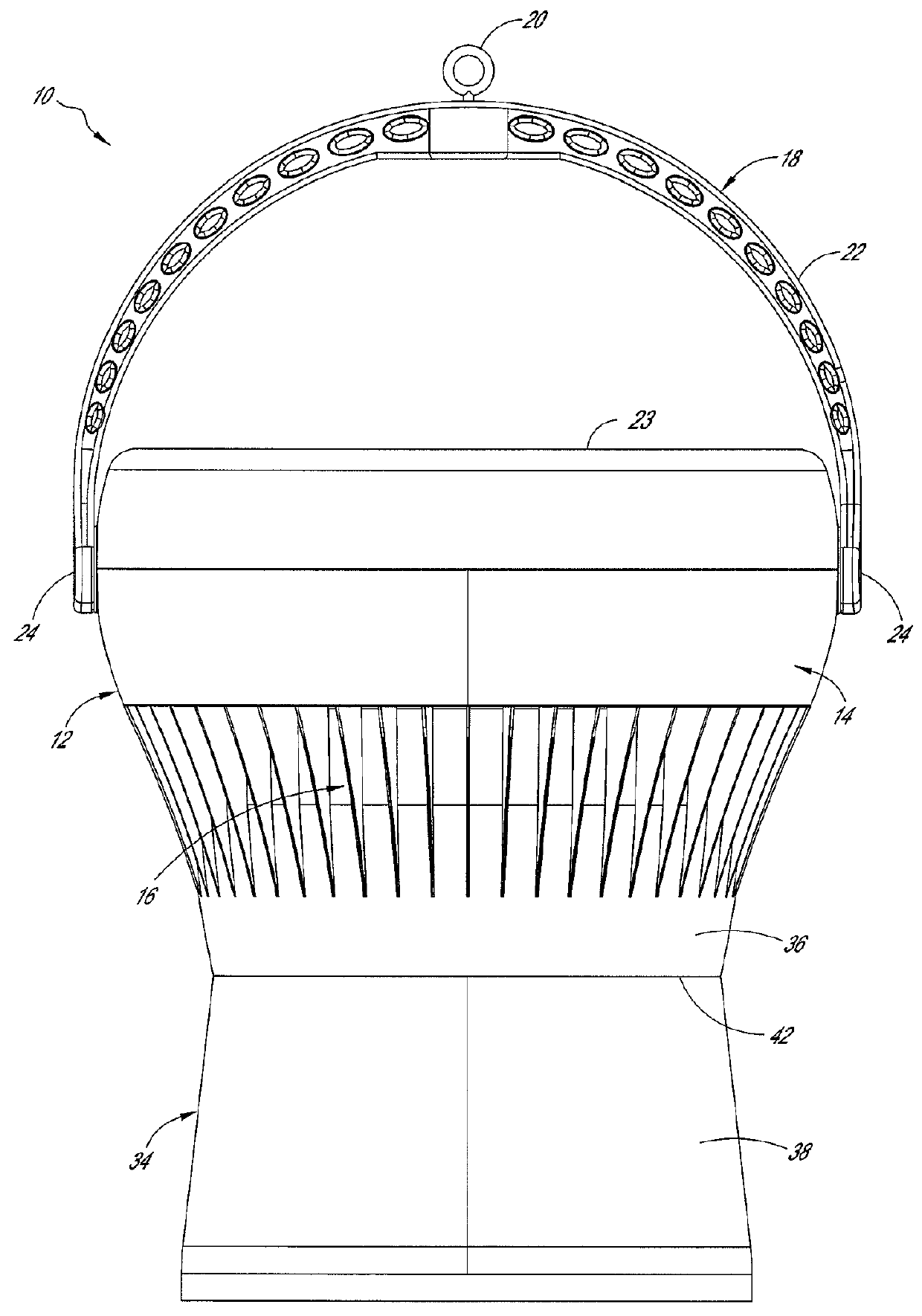
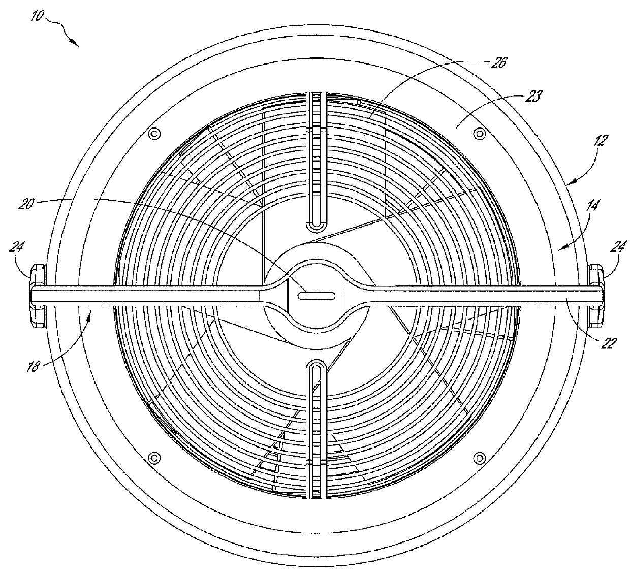
[0031]With reference to FIGS. 1-4, an air moving device 10 can comprise a housing member 12. The housing member 12 can form an outer shell of the air moving device 10, and can at least partially enclose an interior space within the air moving device 10. The housing member 12 can be formed from one or more sections. For example, the housing member 12 can comprise an upper housing section 14, and a lower housing section 16. In some embodiments the upper and lower housing sections 14, 16 can be attached to one other through use of fasteners, adhesive, or other structure. In some embodiments, the upper housing section 14 and lower housing section 16 can be integrally formed as a single piece.

[0032]The air moving device 10 can include a support member 18. The support member 18 can be used to support the weight of the air moving device 10, and / or to attach the air moving device 10 to another structure. In some embodiments, the support member 18 can comprise a ring-shaped structure 20 (e.g...


PUM


Abstract

An air moving device includes a housing member, a rotary fan assembly, and a nozzle. The air moving device further includes a light source member mounted within the nozzle. The light source member can be placed within a flow of air moving out the end of the nozzle in a generally columnar pattern. The flow of air can be used to cool the light source member. A portion of the nozzle can be transparent, allowing the light from the light source member to emanate radially, as well as longitudinally.

Description

CROSS-REFERENCE TO RELATED APPLICATIONS[0001]This application claims benefit under 35 U.S.C. §119(e) to U.S. Provisional Patent Application No. 61 / 497,448, filed Jun. 15, 2011, and to U.S. Provisional Patent Application No. 61 / 521,270, filed Aug. 8, 2011, each of which is incorporated in its entirety by reference herein.[0002]This application is related to U.S. Provisional Patent Application No. 61 / 497,422, entitled Columnar Air Moving Devices, Systems and Methods, filed Jun. 15, 2011, and to U.S. Provisional Patent Application No. 61 / 497,446, entitled Columnar Air Moving Devices, Systems and Methods, filed Jun. 15, 2011, each of which is incorporated in its entirety by reference herein. This application is also related to U.S. patent application Ser. No. 12 / 130,909, filed May 30, 2008, and to U.S. patent application Ser. No. 12 / 724,799, filed Mar. 16, 2010, each of which is incorporated in its entirety by reference herein.BACKGROUND OF THE INVENTIONS[0003]1. Field of the Inventions...

Claims


Application Information

Patent Timeline
Patent Type & Authority Patents(United States)
IPC IPC(8): B60Q1/06F21V29/00F21V33/00F21S8/00F24F7/06F24F13/078
CPCF24F7/065F24F13/078F04D25/088F04D29/545F21V33/0088F21S8/026F21S8/06F21V29/673F04D25/06F04D25/08F04D29/002F04D29/325F04D29/522F04D29/542F04D29/547
Inventor AVEDON, RAYMOND B.
Owner AIRIUS IP HLDG
Why Eureka
Try Eureka