
Columnar air moving devices, systems and methods

a technology of air moving devices and columns, applied in ventilation systems, lighting and heating apparatuses, heating types, etc., can solve the problems of air temperature stratification, significantly increasing heating and air conditioning costs, air temperature stratification problems, etc., to reduce the amount of air passage, reduce the overall energy requirement, and warm the environment

Active Publication Date: 2019-03-05
AIRIUS IP HLDG
View PDF410 Cites 30 Cited by
  • Summary
  • Abstract
  • Description
  • Claims
  • Application Information

AI Technical Summary

Benefits of technology

The patent describes an air de-stratification device that can improve air quality in a grocery store or other enclosure. The device can reduce high temperature areas near the ceiling and direct air in a specific pattern to reduce the amount of air needed. This can save energy and improve safety by reducing the amount of air in narrow areas. The device can also warm the environment in the aisles to make it more comfortable for shoppers and reduce fogging or condensation on refrigeration units. By improving air quality, the device can increase sales and make shopping more enjoyable for customers.

Problems solved by technology

Air temperature stratification is particularly problematic in large spaces with high ceilings such as grocery stores, warehouses, gymnasiums, offices, auditoriums, hangers, commercial buildings, residences with cathedral ceilings, agricultural buildings, and other structures, and can significantly increase heating and air conditioning costs.
Structures with both low and high ceiling rooms can often have stagnant or dead air, as well, which can further lead to air temperature stratification problems.
In some cases, de-stratifying the air in these aisles can dry up water on the floor of the aisle.

Method used


Image

  • Columnar air moving devices, systems and methods
  • Columnar air moving devices, systems and methods
  • Columnar air moving devices, systems and methods

Examples


Embodiment Construction

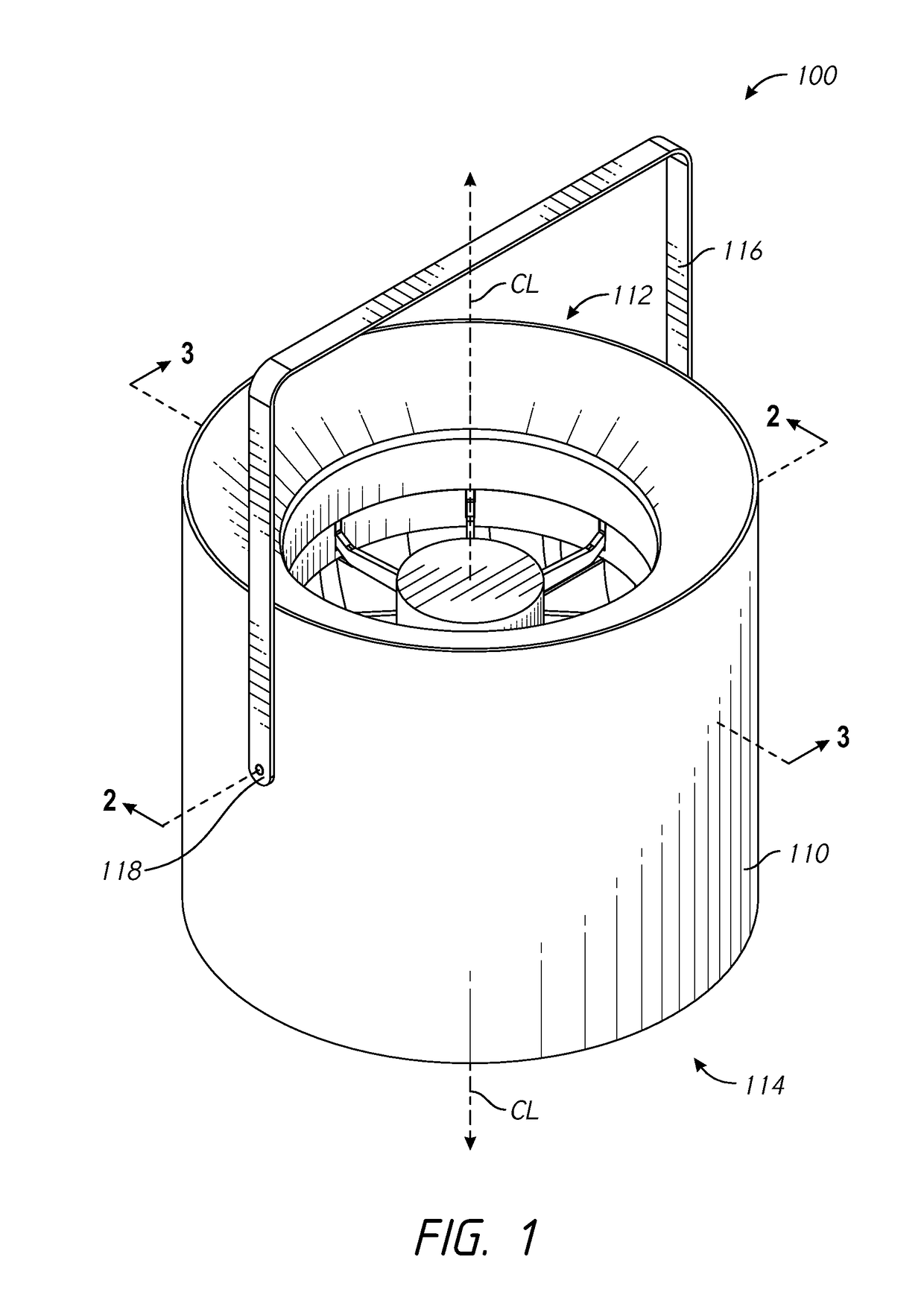
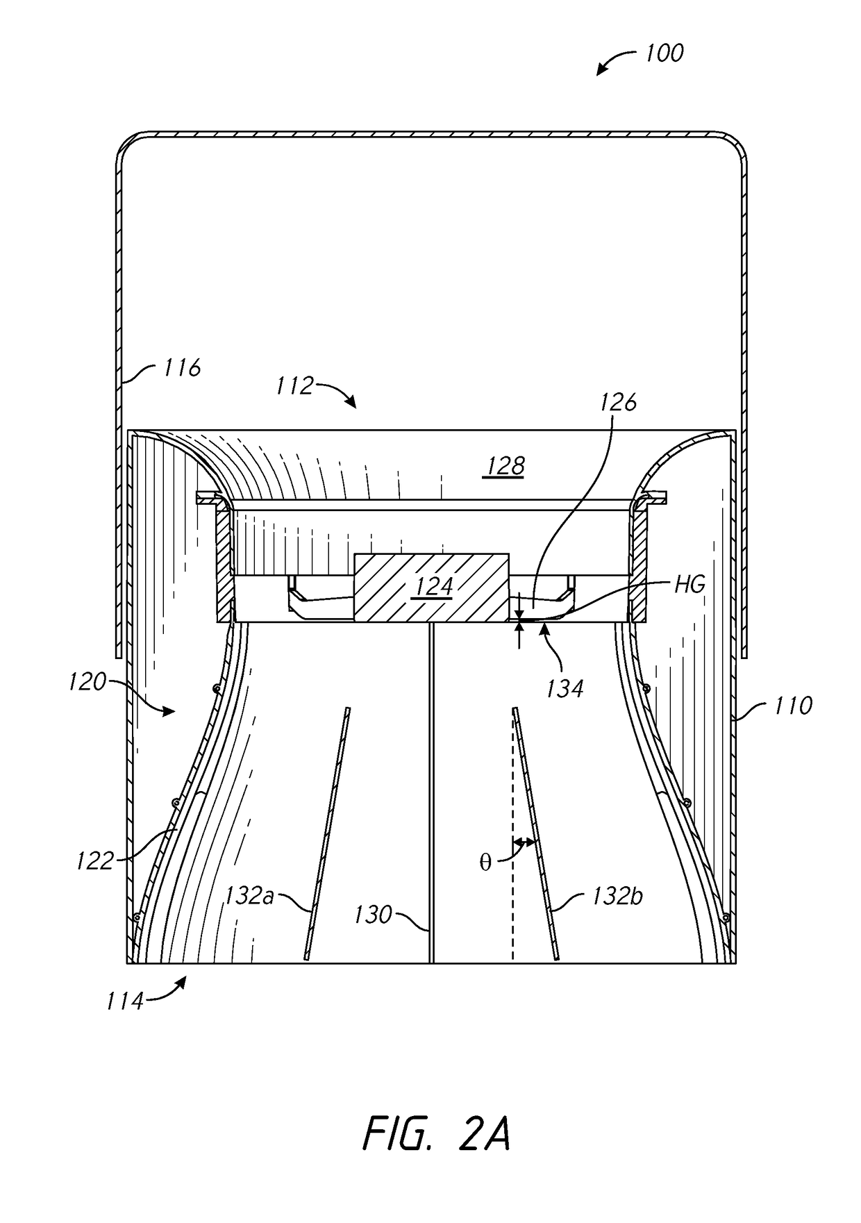
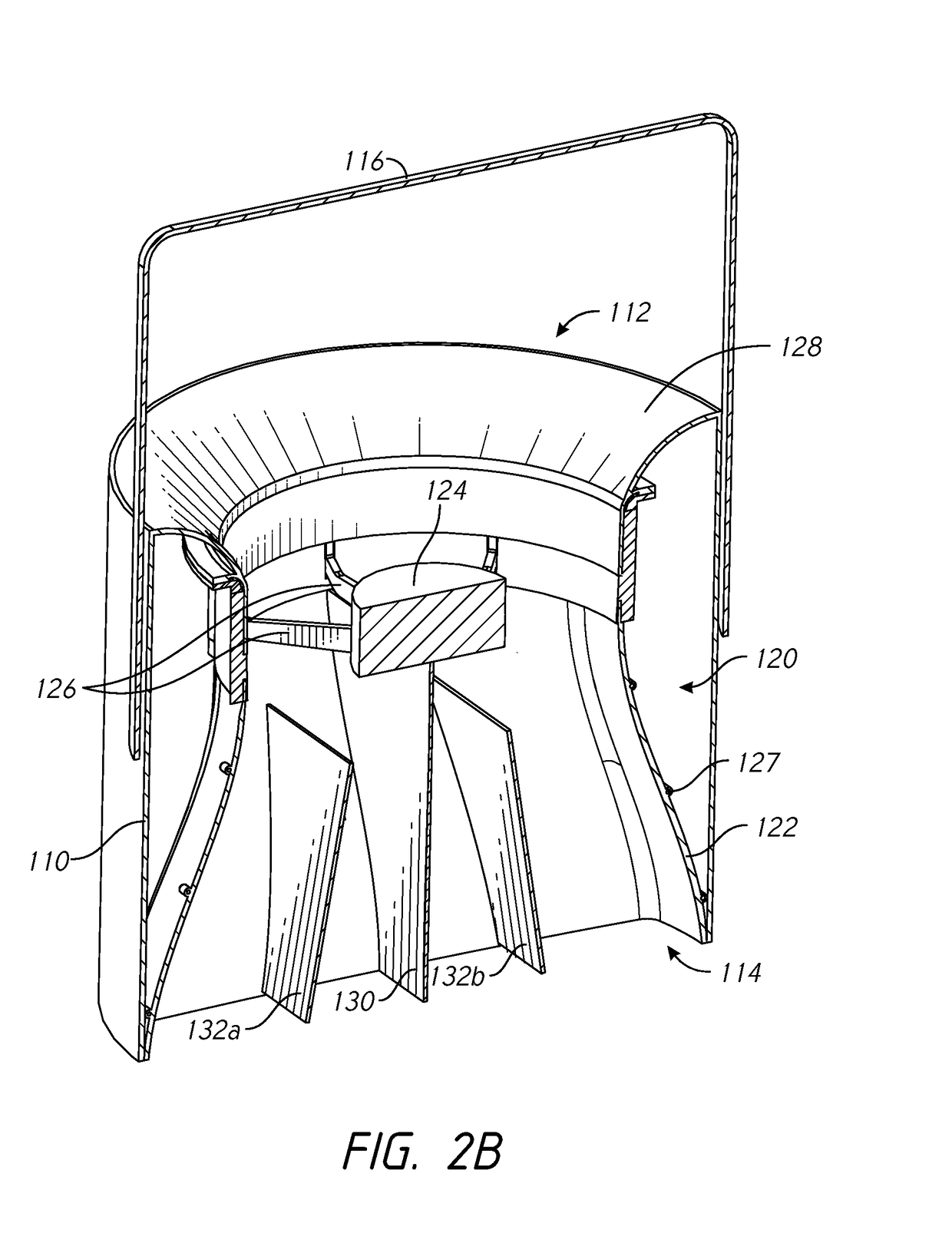
[0030]As illustrated in FIG. 1, an air moving device 100 can include an outer housing 110. The outer housing 110 can have a generally cylindrical shape, though other shapes are possible. For example, the outer housing 110 can have an annularly symmetric shape with varying diameters along a length of the outer housing 110. The air moving device 100 can have an inlet 112 and an outlet 114. As illustrated, the air moving device 100 can have a central axis CL extending through the air moving device 100 between the inlet 112 and the outlet 114.

[0031]A hanger 116 may be attached to the outer housing 110. For example, the hanger 116 may be hingedly attached to the outer housing 110 via one or more hinge points 118. The hanger 116 can facilitate installation of the air moving device 100 at or near a ceiling or other structure within an enclosure (e.g., a warehouse, retail store, grocery store, home, etc.). Further, the hanger 116 may advantageously space the inlet 112 from a mounting surfac...


PUM


Abstract

An air moving device includes a housing member, an impeller assembly, and a nozzle assembly. The nozzle assembly can include one or more angled vanes set an angle with respect to a central axis of the air moving device. The air moving device can output a column of moving air having an oblong and / or rectangular cross-section. A dispersion pattern of the column of moving air upon the floor of an enclosure in which the air moving device is installed can have an oblong and / or rectangular shape. The dimensions of the dispersion pattern may be varied by moving the air moving device toward or away from the floor, and / or by changing the angles of the stator vanes within the nozzle assembly.

Description

RELATED APPLICATIONS[0001]This application claims the benefit of U.S. Provisional Application No. 62 / 008,776, filed Jun. 6, 2014, titled COLUMNAR AIR MOVING DEVICES, SYSTEMS AND METHODS. The entire contents of the above-identified patent application is incorporated by reference herein and made a part of this specification. Any and all priority claims identified in the Application Data Sheet, or any correction thereto, are hereby incorporated by references under 37 CFR § 1.57.FIELD OF THE INVENTIONS[0002]The present application relates generally to systems, devices and methods for moving air that are particularly suitable for creating air temperature de-stratification within a room, building, or other structure.DESCRIPTION OF THE RELATED ART[0003]The rise of warm air and the sinking of cold air can create significant variation in air temperatures between the ceiling and floor of buildings with conventional heating, ventilation and air conditioning systems. Air temperature stratificat...

Claims


Application Information

Patent Timeline
Patent Type & Authority Patents(United States)
IPC IPC(8): F04D29/52F24F7/013F04D25/06F04D13/06F24F7/06F04D19/00F04D25/08F04D29/54
CPCF04D29/547F04D13/06F04D19/002F04D25/0606F04D25/08F04D25/088F24F7/065F04D29/541F04D29/542F04D29/544F24F7/013F24F7/06F04D29/522F04D29/54
Inventor AVEDON, RAYMOND B.
Owner AIRIUS IP HLDG
Learn More