Floating breakwater

a technology of floating breakwaters and breakwaters, which is applied in the direction of hydroelectric engineering, marine site engineering, coastline protection, etc., can solve the problems of prohibitive cost of such breakwaters, floats with relatively shallow drafts and spans, and wave propagation typically cannot be significantly reduced

Active Publication Date: 2016-05-17
KUWAIT INST FOR SCI RES
View PDF12 Cites 9 Cited by
  • Summary
  • Abstract
  • Description
  • Claims
  • Application Information

AI Technical Summary

Problems solved by technology

However, most such floats have relatively shallow drafts and spans, i.e., they do not extend below the surface of the water to a significant degree and do not extend to a significant fraction of the wavelength.
Thus, even when the floating breakwater is moored securely to the sea floor or to a floor of a body of water, wave propagation typically cannot be reduced significantly if the wave action extends beneath the floating breakwater.
While it can be possible to construct floating breakwaters that are sufficiently large as to provide the desired degree of effectiveness, the cost of such breakwaters can be prohibitive when attempting to attenuate large waves and swells.

Method used


Image

  • Floating breakwater
  • Floating breakwater
  • Floating breakwater

Examples


Embodiment Construction

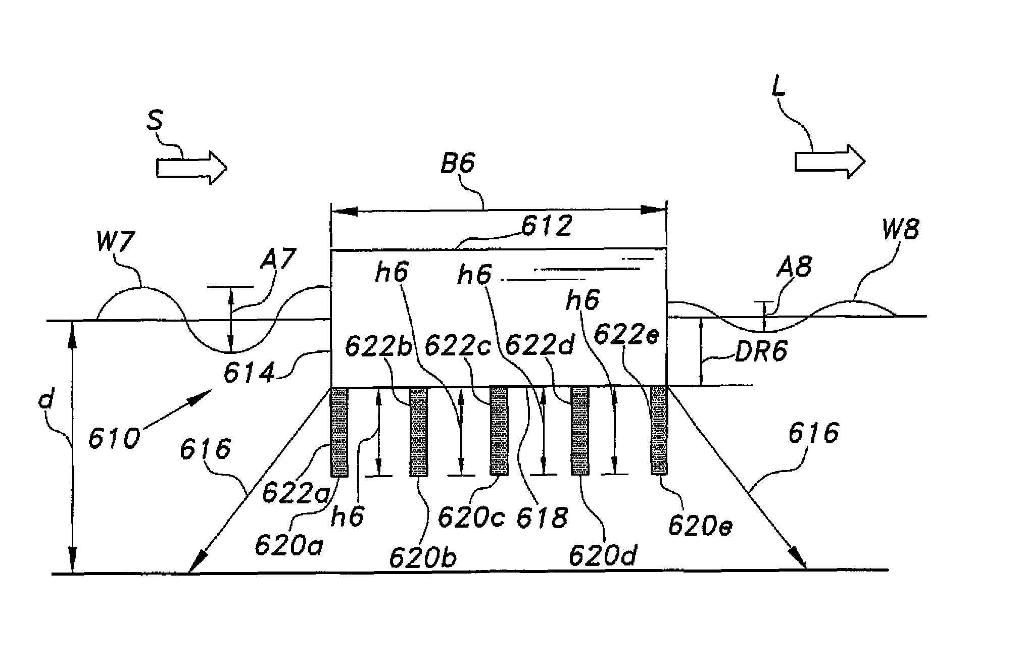
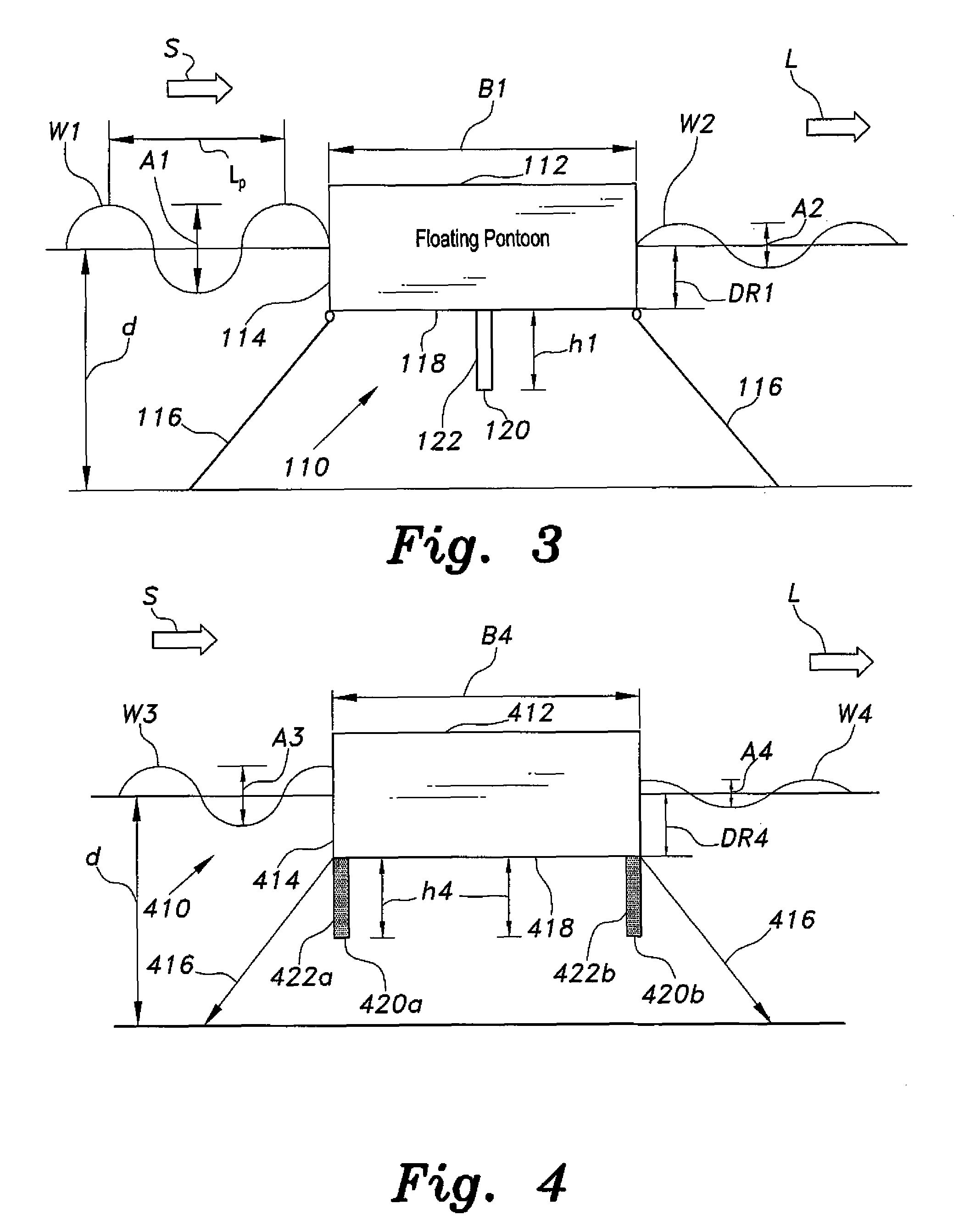
[0022]The floating breakwater includes various embodiments, each having at least one baffle or skirt wall depending therefrom. The one or more baffles or skirt walls can effectively increase the draft or depth of the float, and can serve to interfere with wave circulation beneath the surface of the water and below the bottom of the float to increase the efficiency of the floating breakwater to attenuate the wave action.

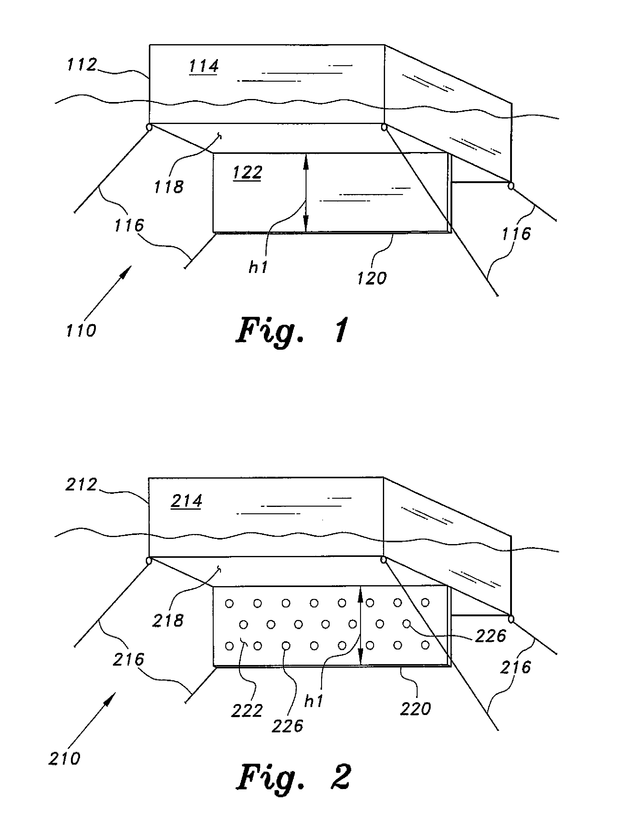
[0023]FIG. 1 of the drawings is a bottom perspective view of an embodiment of a floating breakwater 110. The floating breakwater 110 includes a buoyant float 112, which can be of any suitable shape or configuration. However, the float 112 is desirably in the geometric form of a generally rectangular parallelepiped configuration, as shown in FIG. 1 and in embodiments illustrated in FIGS. 2-6, for example. This configuration can enable the floating breakwater 110 to be installed with one of its two longer vertical surfaces, e.g., the front surface 114, facing directly i...


PUM


Abstract

The floating breakwater includes various different embodiments, as can have an anchored or moored float. The float is desirably in the geometric form of a generally rectangular solid configuration, but can include other forms. One or more baffles or skirt walls extend from the bottom surface of the float, thereby attenuating subsurface wave action to a greater depth than the bottom of the float. Each of the baffles or skirt walls desirably includes a thin, flat, monolithic plate member for enhancing hydrodynamic resistance. The one or more baffles or skirt walls can be continuous and unbroken, or can have a plurality of apertures therethrough. When three or more baffles or skirt walls are provided they can be evenly spaced, or the spacing therebetween can vary. When two or more baffles or skirt walls are provided they can have equal depths, or their depths can differ from one another.

Description

BACKGROUND OF THE INVENTION[0001]1. Field of the Invention[0002]The present invention relates generally to devices and systems for controlling water movement in maritime environments, and more specifically to a floating breakwater having one or more baffles or skirt walls depending therefrom.[0003]2. Description of the Related Art[0004]Breakwaters for the control of wave action in order to prevent damage or destruction of shoreline property and / or environment have been known for a considerable period of time. Perhaps most such breakwaters are permanent installations formed of rock, concrete, scrapped automobiles and / or ships, or other reasonably economical and durable materials.[0005]It was discovered that it is not necessary to construct a breakwater that extends up from the sea floor, as wave action is typically confined to the upper strata of the water. Accordingly, it has been found that reasonably large floats can also provide the desired attenuation of wave action, when provid...

Claims


Application Information

Patent Timeline
Patent Type & Authority Patents(United States)
IPC IPC(8): E02B3/06E02B3/04
CPCE02B3/04E02B3/062
Inventor NEELAMANI, SUBRAMANIAMAL-BANAA, KHALED
Owner KUWAIT INST FOR SCI RES
Why Eureka
Try Eureka