
Floating floor system, floor panel, and installation method for the same

a floating floor and floor technology, applied in the direction of flooring, construction, building components, etc., can solve the problems of difficult use of the methods of assembling floorboards with wood based cores, difficult installation/assembly process, and difficulty in removing adjacent floor panels, etc., to achieve the effect of preventing ledging and minimizing the distance between

Active Publication Date: 2016-05-24
AHF LLC D B A AHF PROD
View PDF27 Cites 22 Cited by
  • Summary
  • Abstract
  • Description
  • Claims
  • Application Information

AI Technical Summary

Benefits of technology

The present invention is a floating floor system and floor panels with a snap-fit locking assembly that provides vertical locking between adjacent floor panels to minimize and prevent ledging therebetween. The snap-fit locking assembly comprises a locking member and a locking slot, which when engaged, vertically lock the floor panels together via mechanical interaction between the undercut surface of the locking member and a locking surface of the second panel. The floor panels can be resilient floor panels, such as LVT, and the snap-fit locking assembly ensures stability and durability of the floor system. The invention also includes a method for installing the floor panels to create a floating floor system.

Problems solved by technology

One problem, with these existing mechanical interlocking systems is that the teeth are not easily alignable with the slots, thereby making the installation / assembly process difficult.
Additionally, these mechanical interlock systems are limited to providing horizontal locking and, thus, ledging between adjacent floor panels can become an issue.
The known methods of assembling floorboards with a wood based core that are mentioned above are difficult to use when assembling resilient floor panels, as resilient floor panes are not rigid and have a thin profile, thereby allowing the floor panels to be easily bent.
Thus, the use of the angle-angle method is difficult.
In addition, the use of the angle-snap method is rendered impracticable since it requires a force to be applied at an opposite edge in relation to the edge of the floor panel which is intended to be connected, by e.g. a hammer and a tapping block, and the resilient core of the resilient floor panel absorbs the applied force and will likely undergo some damage which may be visually undesirable for an end user.
The known vertical folding methods are also difficult to apply due to the increased flexibility of the resilient floor pane allowing the resilient floor panels to disengage more easily than a rigid based floorboard using the same method.
The angled type of a lock on the long side, the short side, or both is significantly more difficult to install than a lock that can be pushed down or snapped down vertically.
However, the vertical fold or push down type locks currently in the market can easily pop open or exhibit “ledging” on square edge products due to subfloor irregularities or any significant relative vertical movement between two locked planks.
The issue with ledging is becoming increasingly pronounced, as do-it-yourself (DIY) type products need to have a square edge (and not a beveled edge) because these products must be price competitive, which means that the DIY products cannot have a thick wear layer which is needed for a beveled edge product.

Method used


Image

  • Floating floor system, floor panel, and installation method for the same
  • Floating floor system, floor panel, and installation method for the same
  • Floating floor system, floor panel, and installation method for the same

Examples


Embodiment Construction

[0027]The following description of the preferred embodiment(s) is merely exemplary in nature and is in no way intended to limit the invention, its application, or uses. The description of illustrative embodiments according to principles of the present invention is intended to be read in connection with the accompanying drawings, which are to be considered part of the entire written description. Moreover, the features and benefits of the invention are illustrated by reference to the exemplified embodiments. Accordingly, the invention expressly should not be limited to such exemplary embodiments, which illustrate some possible non-limiting combinations of features that may exist alone or in other combinations of features; the scope of the invention being defined by the claim appended hereto.

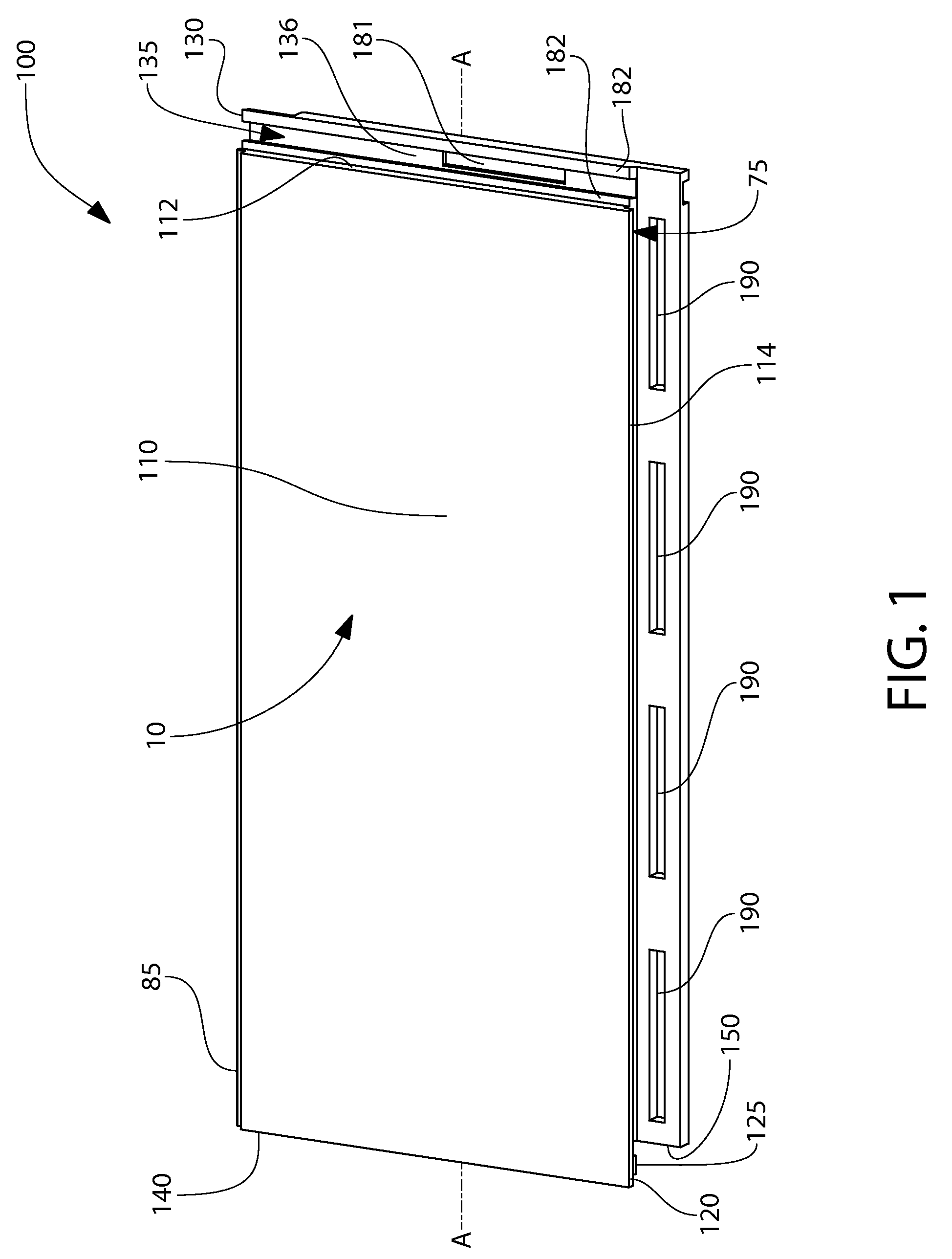
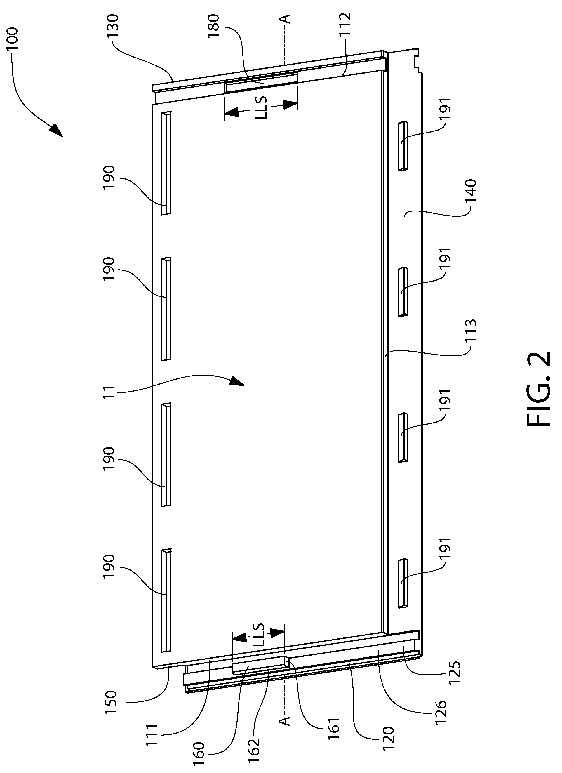
[0028]Referring first to FIGS. 1-4 concurrently, a floor panel 100 according to an embodiment of the present invention is illustrated. In one embodiment, the floor panel 100 may be a vinyl tile, ha...


PUM

PropertyMeasurementUnit
thicknessaaaaaaaaaa
thicknessaaaaaaaaaa
thicknessaaaaaaaaaa

Abstract

A floating floor system and a floor panel and method for use with the same that includes a snap-fit locking assembly that provides vertical locking between adjacent floor panels to minimize and / or prevent ledging therebetween. In one embodiment, a protuberance and a recess are also provide on the floor panels to provide horizontal locking. The snap-fit locking assembly comprises: a locking member protruding from a first flange and comprising an undercut surface; and a locking slot formed in a second flange. The snap-fit locking assembly is configured so that when the locking member of a first one of the panels is disposed within the locking slot of a second one of the panels, the first and second panels are vertically locked together via mechanical interaction between the undercut surface of the locking member of the first panel and a locking surface of the second flange of the second panel.

Description

CROSS-REFERENCE TO RELATED PATENT APPLICATIONS[0001]The present application claims the benefit of U.S. Provisional Patent Application Ser. No. 61 / 623,670, filed Apr. 13, 2012, the entirety of which is incorporated herein by reference.FIELD OF THE INVENTION[0002]The present invention relates generally to floor systems, floor panels, and installation methods thereof, and particularly to an enhanced mechanical lock system for said floor systems, floor panels, and installation methods thereof. The present invention is particularly suited for floating floor systems, such as those that utilize resilient panels, such as LVT (Luxury Vinyl Tile).BACKGROUND OF THE INVENTION[0003]Floating floor systems are known in the art. In existing floating floor systems, the floor panels are typically interlocked together via chemical adhesion. For example, the floor panels of existing floating floor systems generally comprise a lower lateral flange and an upper lateral flange extending from opposite side...

Claims


Application Information

Patent Timeline
Patent Type & Authority Patents(United States)
IPC IPC(8): E04F15/02E04F15/10
CPCE04F15/02022E04F15/02038E04F15/105E04F2201/0146E04F2201/0176E04F2201/021E04F2201/0535E04C2/38E04C2/50E04F15/10E04F2201/03
Inventor RAMACHANDRA, SUNILTOTARO, ANNA J.
Owner AHF LLC D B A AHF PROD
Learn More