Caliper brake device for railway vehicles

a brake device and railway vehicle technology, applied in the direction of brake systems, mechanical devices, transportation and packaging, etc., can solve the problems of affecting the operation of the brake device, the actuator rod protruding, and the entire device becomes bulky, and achieves the effect of eliminating the hydraulic sour

Active Publication Date: 2016-06-21
NIPPON STEEL CORP
View PDF19 Cites 8 Cited by
  • Summary
  • Abstract
  • Description
  • Claims
  • Application Information

AI Technical Summary

Benefits of technology

[0011]According to the present invention, the pneumatic actuator that allows the caliper lever to rotate can be downsized, so as to be replaceable with a hydraulic caliper device without a necessity of remodeling the truck, and abolition of a hydraulic source can be inexpensively achieved.

Problems solved by technology

Accordingly, the entire device becomes bulky, and such a bulky device is difficult to install within a limited space.
Moreover, in the pneumatic caliper brake device proposed in Patent Reference 1, the above problem may be escalated because as the brake shoe gets worn out, the distance of protrusion of the actuator rod during braking may become longer, which may result in requiring a longer stroke of the rod.

Method used


Image

  • Caliper brake device for railway vehicles
  • Caliper brake device for railway vehicles
  • Caliper brake device for railway vehicles

Examples


embodiment

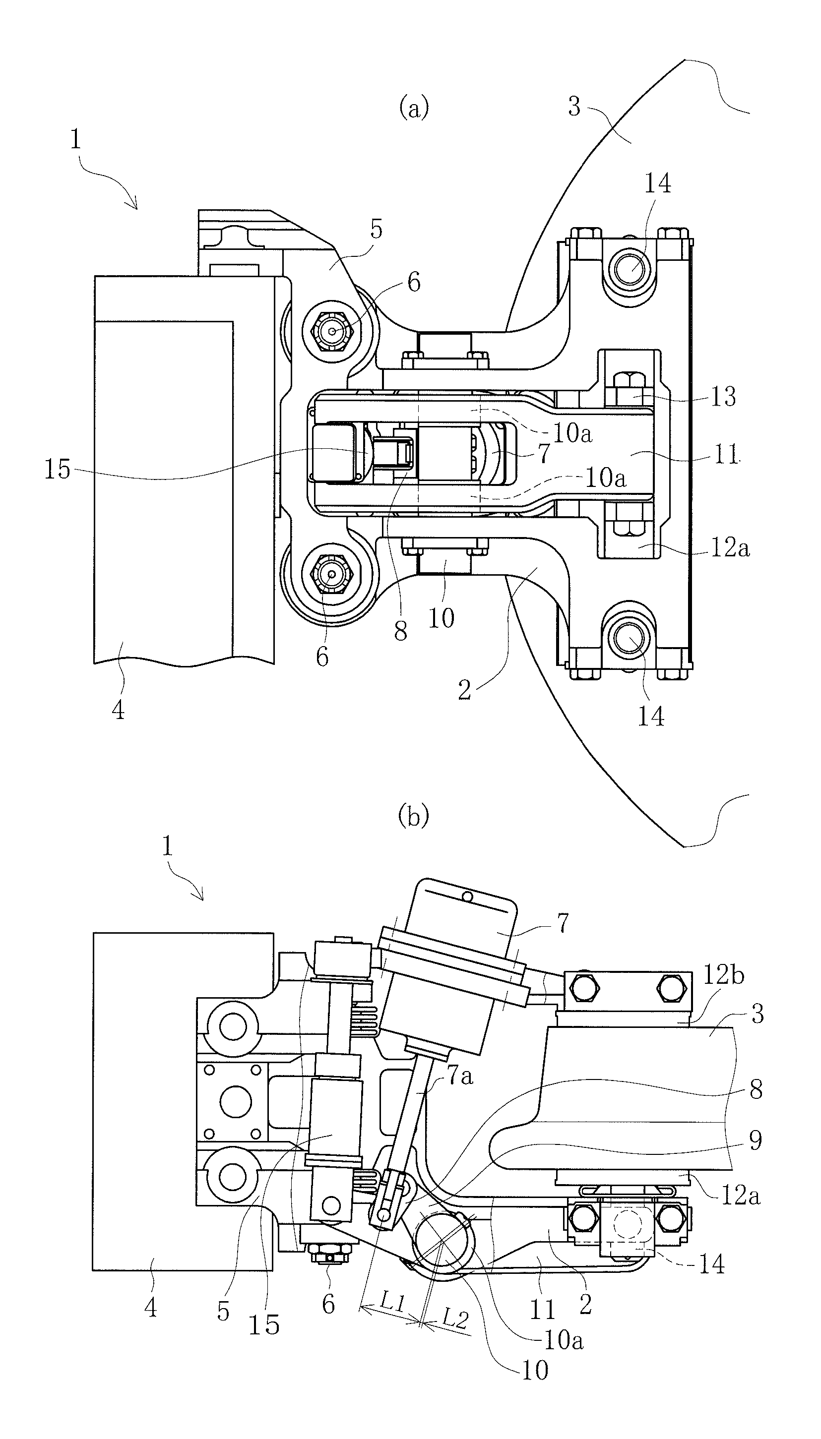
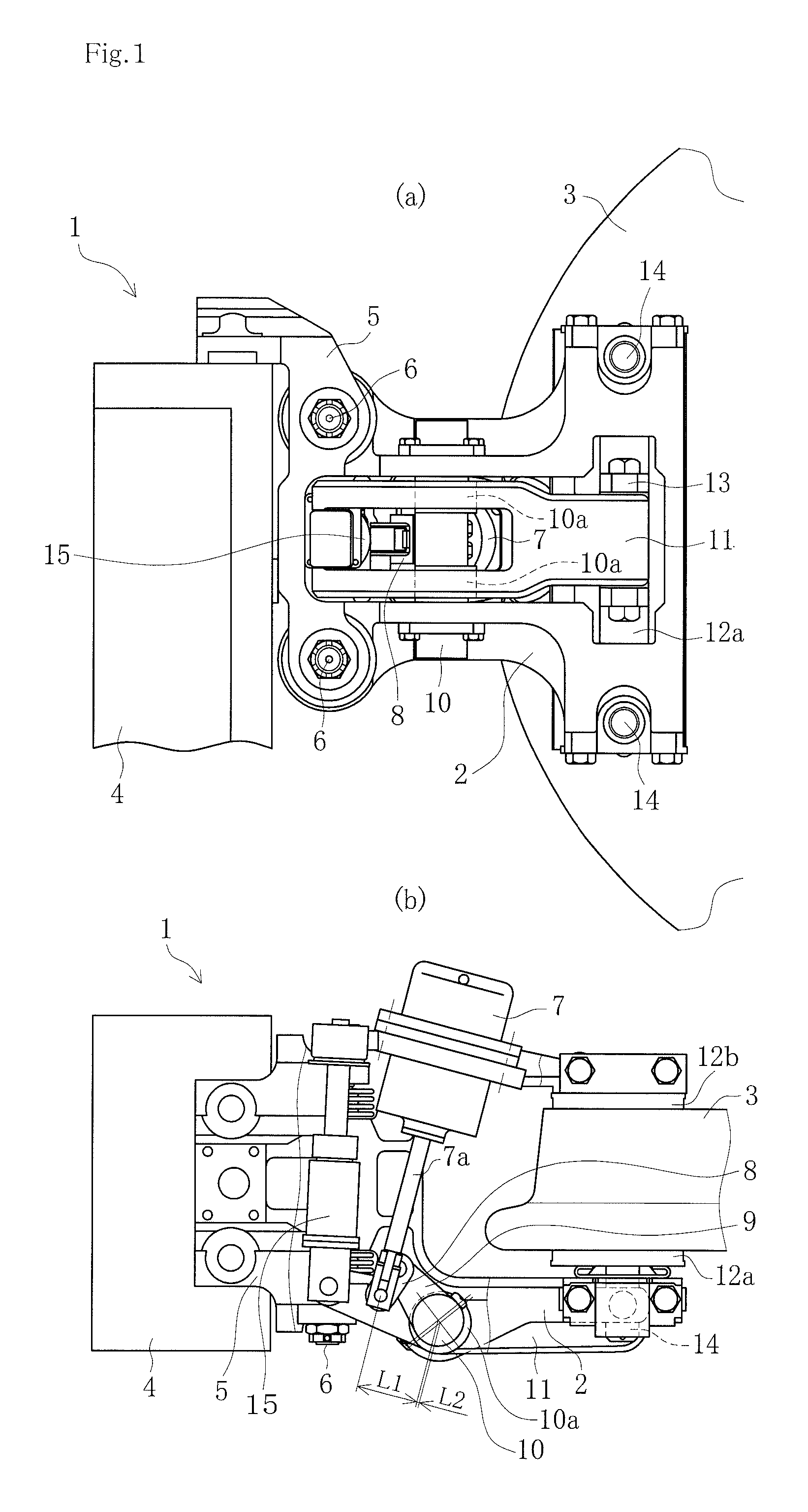
[0018]Exemplary embodiments for implementing the present invention are explained in detail below with reference to FIGS. 1 to 3. Reference numeral 1 denotes a floating-type caliper brake device according to the present invention in which a caliper body moves in an axial direction of a wheel by using a pneumatic actuator. The floating-type caliper brake device has the configuration as explained below.

[0019]Reference numeral 2 denotes a caliper body having a base end portion that is coupled to a support frame 5 so that the caliper body is freely slidable along two support pins 6 installed on the support frame 5 in an axial direction of a wheel 3, and a tip end portion branched off into two parts in which one part is located close to an outside of one outer peripheral side surface and the other part is located close to an outside of other outer peripheral side surface of the wheel 3. The support frame 5 is attached to a truck 4.

[0020]Reference numeral 7 denotes a pneumatic actuator, wh...


PUM


Abstract

A caliper body is slidably attached to a truck in the axial direction of a wheel. The body has a tip end portion branched off into two parts. One part is close to an outside of one side of the wheel with another part close to an outside of the other side of the wheel. An operating lever is arranged that rotates, via a protruding-retreating motion of a pneumatic actuator rod, one end side via a connecting link around an eccentric axis, which is rotatably supported by one of branched-off parts of the caliper body, as a center. One brake shoe is slidably installed to an anchor pin of the caliper body to freely rotate on a tip side inner surface of a caliper lever installed in an eccentric part. Another brake shoe is installed on a tip side inner surface of the other branched-off part of the caliper body.

Description

TECHNICAL FIELD[0001]The present invention relates to a caliper brake device that applies braking force on both side surfaces of a wheel of a railway vehicle by holding respective disks that rotate integrally with the wheel from outside on both side surfaces of the wheel.BACKGROUND ART[0002]A pneumatic-hydraulic converter is required when a hydraulic caliper brake device, which uses hydraulic oil as a pressure medium, is to be used in a railway vehicle in which air is used as the pressure medium. Accordingly, the general trend is to use a pneumatic caliper brake device to abolish a hydraulic source.[0003]However, in order to use the pneumatic caliper brake device, which generates less force than the hydraulic caliper brake device, in a railway vehicle, a larger actuator becomes necessary. Accordingly, the entire device becomes bulky, and such a bulky device is difficult to install within a limited space.[0004]In this regard, Patent Reference 1 proposes a device in which a smaller pn...

Claims


Application Information

Patent Timeline
Patent Type & Authority Patents(United States)
IPC IPC(8): F16D55/08B61H15/00F16D65/14B60T13/36F16D65/46F16D65/56F16D55/224B61H5/00F16D65/18
CPCB61H5/00B61H15/00F16D65/14F16D65/18F16D65/46F16D65/56F16D55/2245B60T13/365
Inventor TSURUSAKI, AKITOYOKOTA, HIRONORIKAMIMURA, KENICHIRO
Owner NIPPON STEEL CORP
Why Eureka
Try Eureka