Artificial intelligence for detecting and filling void areas of agricultural commodity containers

a technology of artificial intelligence and agricultural commodity containers, applied in the field of agricultural material transfer, can solve the problem that the operator may not have a clear line of sight, and achieve the effect of facilitating the transfer of agricultural materials

Active Publication Date: 2016-07-19
DEERE & CO +1
View PDF53 Cites 45 Cited by
  • Summary
  • Abstract
  • Description
  • Claims
  • Application Information

AI Technical Summary

Problems solved by technology

Controlling the spout position while maintaining cooperative alignment is a challenging process because an operator of the harvesting machine must monitor various controls relating to harvesting the crop in front of the harvesting machine, while simultaneously monitoring and controlling the material transfer process to the side of the harvesting machine.
Further difficulties arise because the operator may not have a clear line of sight into the storage portion.

Method used


Image

  • Artificial intelligence for detecting and filling void areas of agricultural commodity containers
  • Artificial intelligence for detecting and filling void areas of agricultural commodity containers
  • Artificial intelligence for detecting and filling void areas of agricultural commodity containers

Examples


example void

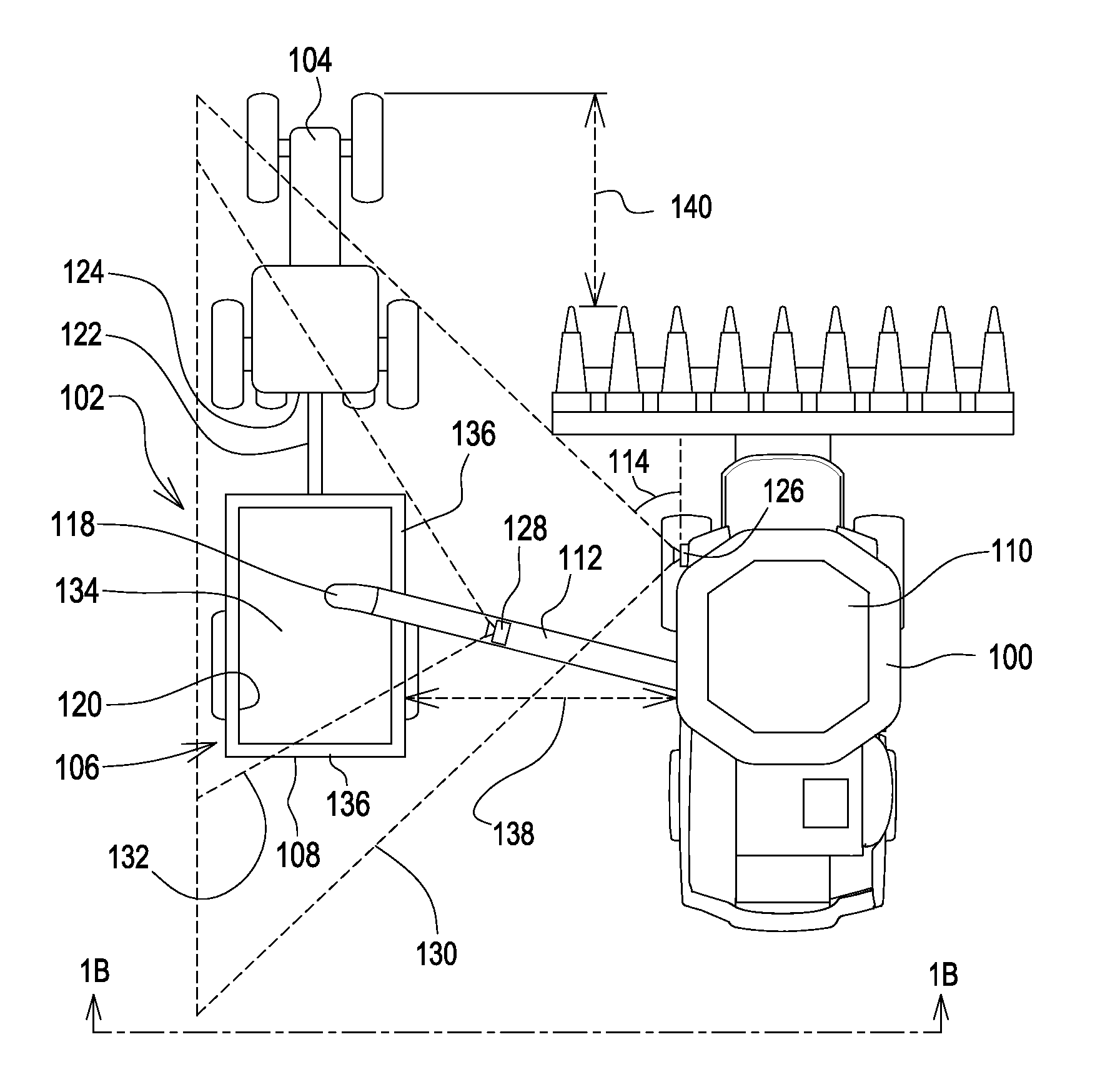
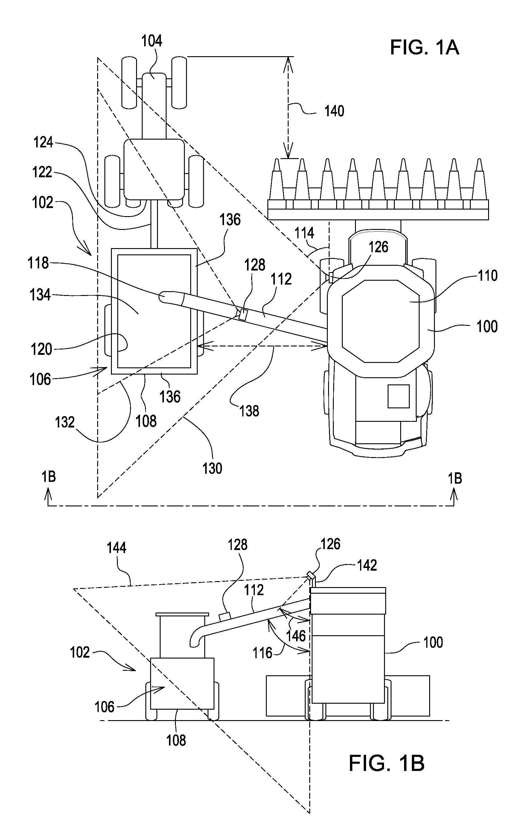
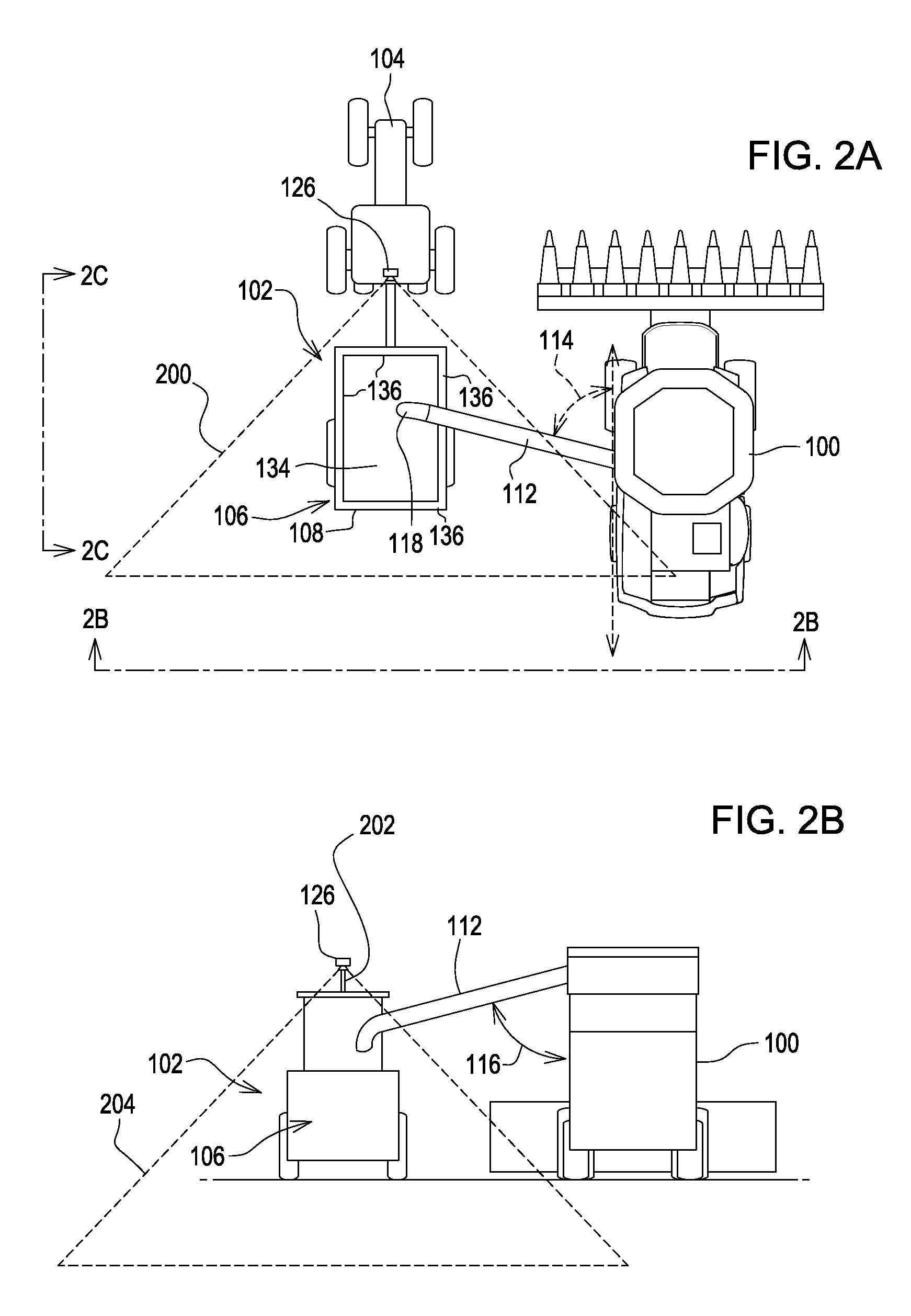
[0129 filling modes 1400 may include further steps to control the order in which voids are filled. In one example, the void filling mode 1400 may command the spout 112 to sweep from back-to-front or front-to-back and selectively fill voids as they are identified. In another example, the void filling mode 1400 may begin by filling the void with the largest void volume and sequentially filling smaller voids until all voids are filled. Certain examples utilize a control strategy that minimizes actuation energy of the spout 112 by minimizing movement of the spout 112. Other examples may restrict the void filling mode to portions of a zone depending on the material distribution within the storage portion 106. In an example in which the void filling mode 1400 is entered within a zone prior to all of the zones being considered full, the void filling mode 1400 may ignore portions of a zone that are adjacent cells or columns having lower fill levels. Otherwise, voids may be falsely identifie...


PUM


Abstract

A system and method for transferring agricultural material from a transferring vehicle to a storage portion of a receiving vehicle, and detecting and filling void areas of the agricultural material is disclosed. A transferring vehicle having a spout transfers agricultural material to a storage portion of a receiving vehicle. An imaging device associated with the transferring vehicle and facing towards the storage portion of the receiving vehicle collects imaging data. An image processing module is operable to, based on the imaging data, estimate fill levels of agricultural material within the storage portion; identify an area of the storage portion as targeted to fill; and identify a first void within the targeted area. A controller in communication with the image processing module is configured to command the spout to a position to direct agricultural material to the first void.

Description

RELATED APPLICATIONS[0001]This patent claims the benefit of U.S. Provisional Patent Application Ser. No. 61 / 859,286, filed Jul. 28, 2013. This patent is also a continuation-in-part of U.S. patent application Ser. No. 13 / 763,288, filed on Feb. 8, 2013, which claims the benefit of U.S. Provisional Patent Application Ser. No. 61 / 597,380, filed Feb. 10, 2012. U.S. Provisional Patent Application Ser. No. 61 / 859,286, U.S. patent application Ser. No. 13 / 763,288, and U.S. Provisional Patent Application Ser. No. 61 / 597,380 are incorporated herein by reference in their entirety.JOINT RESEARCH AGREEMENT[0002]This application resulted from work performed under or related to a joint research agreement between Iowa State University and Deere & Company, entitled “Iowa State University Master Research Agreement,” dated Jan. 1, 2006, as amended in an Amendment dated Jan. 1, 2011, and as such is entitled to the benefits available under 35 U.S.C. §103(c).FIELD OF THE INVENTION[0003]The present disclos...

Claims


Application Information

Patent Timeline
Patent Type & Authority Patents(United States)
IPC IPC(8): A01D43/073A01D43/08
CPCA01D43/073A01D43/087
Inventor DARR, MATTHEW J.MCNAULL, ROBERTKRUCKEBERG, JOHNBONEFAS, ZACHARY T.
Owner DEERE & CO
Why Eureka
Try Eureka