Electric power conversion apparatus

a technology of electric power conversion and converter, which is applied in the direction of dc-ac conversion without reversal, process and machine control, instruments, etc., can solve the problems of non-optimized efficiency of the overall system efficiency and the loss of conversion operation and switching, so as to reduce the unnecessary operation and conversion operation of the converter. , the effect of solving the unnecessary operation and conversion loss of the converter

Active Publication Date: 2016-07-26
LSIS CO LTD +1
View PDF5 Cites 2 Cited by
  • Summary
  • Abstract
  • Description
  • Claims
  • Application Information

AI Technical Summary

Benefits of technology

[0011]Accordingly, in order to solve the unnecessary operation and switching loss of a converter in the related art, that task of the present disclosure is to provide an electric power conversion apparatus capable of determining a minimum output voltage of a boost converter based on a voltage of the grid, and comparing the minimum output voltage of the converter with an input voltage of the converter, and controlling the operation of the converter based on the comparison result, thereby reducing the unnecessary operation and switching loss of the converter.

Problems solved by technology

In the related art, the DC / DC boost converter is operated all the time, thus causing the switching loss of the converter as well as leading to a non-optimized efficiency of the overall system efficiency due to unnecessary electric power conversion.

Method used


Image

  • Electric power conversion apparatus
  • Electric power conversion apparatus
  • Electric power conversion apparatus

Examples


embodiment 1

Switching Control of Converter

[0107]Embodiment 1 disclosed in the present disclosure may be implemented by any part or combination of the configuration or process included in the foregoing embodiments or implemented by a combination of the embodiments, and technological terms used herein are merely used to describe a specific embodiment, but not to limit the present invention.

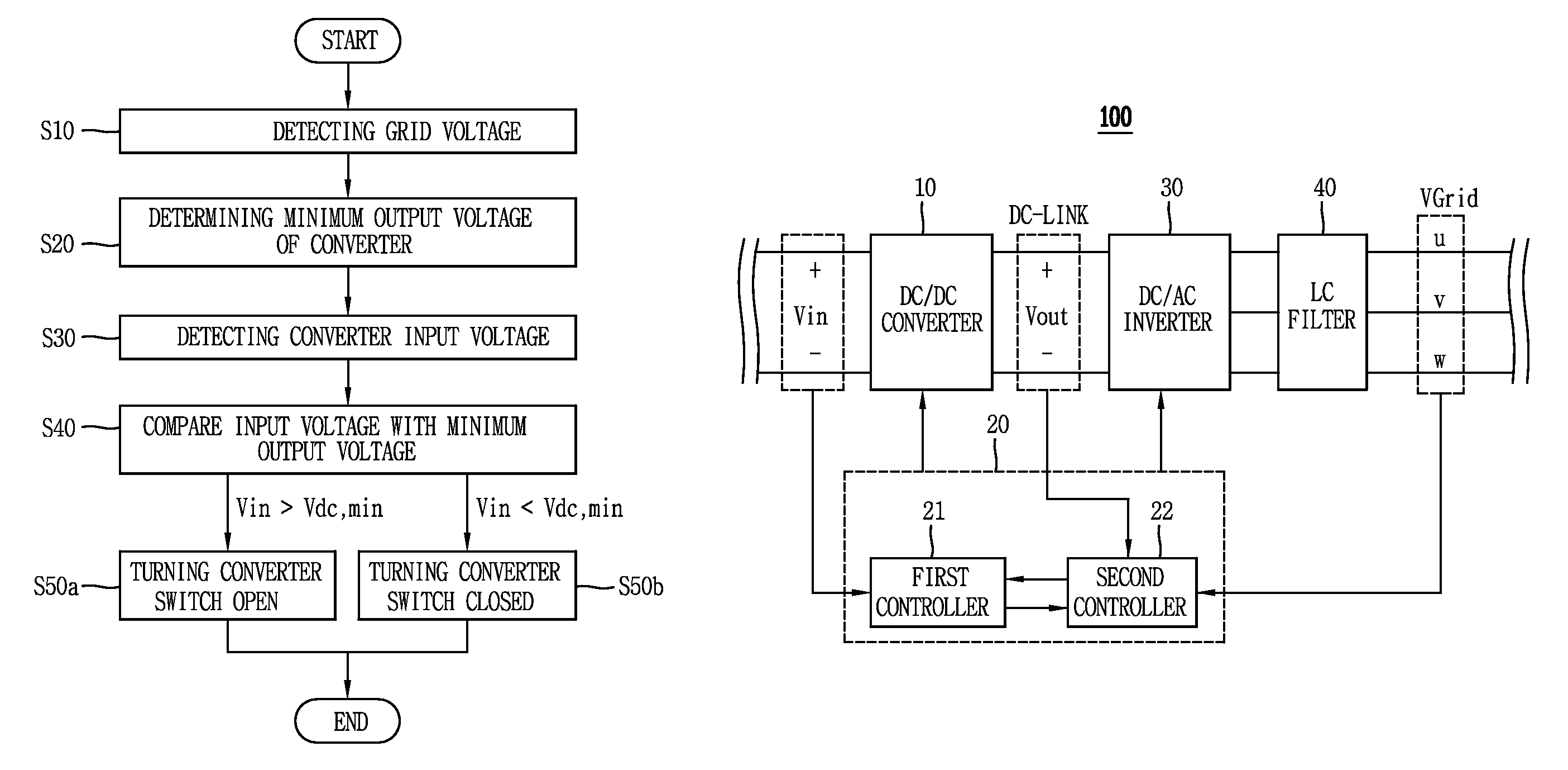
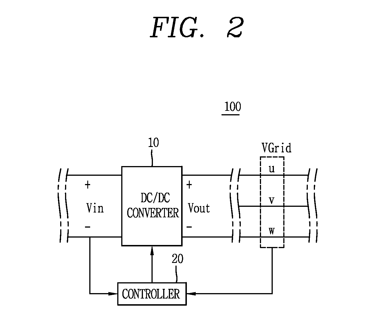
[0108]The electric power conversion apparatus 100 comprises a converter 10, and a control unit 20 configured to detect a grid voltage so that the control unit 20 determines a minimum output voltage of the converter 10 based on the grid voltage, and control the operation of the converter 10 based on an input voltage of the converter and the determined minimum output voltage, and may further comprise an inverter 30 linked to an output stage of the converter 10 and an LC filter 40 linked between the inverter 30 and the grid.

[0109]And the controller contained in the electric power conversion apparatus 100 may inclu...

embodiment 2

Boosting Operation Control of Converter

[0116]Embodiment 2 disclosed in the present disclosure may be implemented by any part or combination of the configuration or process included in the foregoing embodiments or implemented by a combination of the embodiments, and technological terms used herein are merely used to describe a specific embodiment, but not to limit the present invention.

[0117]The electric power conversion apparatus 100 comprises a converter 10, and a control unit 20 configured to detect a grid voltage to determine a minimum output voltage of the converter 10 based on the grid voltage, and control the operation of the converter 10 based on an input voltage of the converter and the determined minimum output voltage. The electric power conversion apparatus 100 may further comprise an inverter 30 linked to an output stage of the converter 10 and an LC filter 40 linked between the inverter 30 and the grid. And the control unit 20 contained in the electric power conversion ...


PUM


Abstract

The disclosure relates to an electric power conversion apparatus, and capable of determining a minimum output voltage of a boost converter based on a voltage of the grid, and comparing the minimum output voltage of the converter with an input voltage of the converter, and controlling the operation of the converter based on the comparison result, thereby reducing the unnecessary operation and switching loss of the converter, the electric power conversion apparatus according to the invention comprises a converter; and a control unit configured to detect a grid voltage to determine a minimum output voltage of the converter based on the grid voltage, and control the operation of the converter based on an input voltage of the converter and the determined minimum output voltage.

Description

CROSS-REFERENCE TO RELATED APPLICATIONS[0001]Pursuant to 35 U.S.C. §119(a), this application claims the benefit of earlier filing date and right of priority to Korean Application No. 10-2013-0112038, filed on Sep. 17, 2013, the contents of which are all hereby incorporated by reference herein in its entirety.BACKGROUND OF THE INVENTION[0002]1. Field of the Invention[0003]The present disclosure relates to an electric power conversion apparatus, and more particularly, to the electric power conversion apparatus capable of determining a minimum output voltage of a boost converter for boosting a DC voltage to compare it with an input voltage of the converter, and controlling the operation of the converter based on the comparison result so as to reduce an unnecessary operation of the converter.[0004]2. Description of the Related Art[0005]The operation of a typical multi-string photovoltaic system is carried out by controlling a plurality of photovoltaic cell generators and converters conn...

Claims


Application Information

Patent Timeline
Patent Type & Authority Patents(United States)
IPC IPC(8): H02M7/48H02M7/5387H02J3/38H02M3/156H02M1/00
CPCH02M7/53871H02M7/48H02M7/4807H02M7/4826H02J3/385H02M3/156H02M2001/007H02M2001/0025H02M2001/0048H02M2001/0054Y02B70/1491Y02E10/58H02J2300/26H02J3/381Y02B10/10Y02B70/10Y02E10/56H02M1/0025H02M1/0048H02M1/007H02J2300/24H02J3/46H02M1/0054
Inventor YOO, ANNOHA, JUNG IKSHIN, HO JOONHYUNG, KWON YUB
Owner LSIS CO LTD
Why Eureka
Try Eureka