
Universal adapter for light-modifying devices

a technology of adapters and modifiers, applied in the field of illumination devices, can solve the problems of small size, low power, and difficulty in using a modifier built for a hot shoe strobe with a studio strob

Inactive Publication Date: 2016-08-16
ORILI VENTURES
View PDF5 Cites 57 Cited by
  • Summary
  • Abstract
  • Description
  • Claims
  • Application Information

AI Technical Summary

Benefits of technology

The present invention provides an adapter that integrates a strobe modifier with a light reflector and strobe light source. The adapter is easy to adjust, protected, and universal. The adapter has an optional connecting arm that folds and includes a moveable bolt and retaining nut. The light modifying device also comprises a light modifier and the connecting arm interconnects to a lighting modifier. The shroud extends from behind the arms and is optionally supported by a ring that engages the outer surface of each arm. The internal surface of the shroud is covered with light reflecting material. The technical effects include improved flexibility, protection, and easy adjustment of the light modifying device.

Problems solved by technology

They are typically small in size, powered by batteries, and relatively low in power.
The nature of those two very different connections makes it difficult to use a modifier built for a hot shoe strobe with a studio strobe.
Moving a strobe lighting modifier from one position to another during a photographic session can cause the strobe lighting modifier to lose its orientation relative to the strobe light source because of jiggling, rocking or other movements.
Using strobes and light reflectors of different sizes and intensities causes time delays due to re-fitting the devices together after readjustment and substitution.
The commercially available hot shoe strobe modifiers are provided by various manufacturers with proprietary adapters, and there are no uniform standards that facilitate the use of the modifier of one manufacturer with the lighting source of another.
Moreover, lighting modifiers for studios can be more complicated than non-studio lighting modifiers and the additional equipment necessary for both studio and non-studio photography can add to the costs and bulk of photography.

Method used


Image

  • Universal adapter for light-modifying devices
  • Universal adapter for light-modifying devices
  • Universal adapter for light-modifying devices

Examples


Embodiment Construction

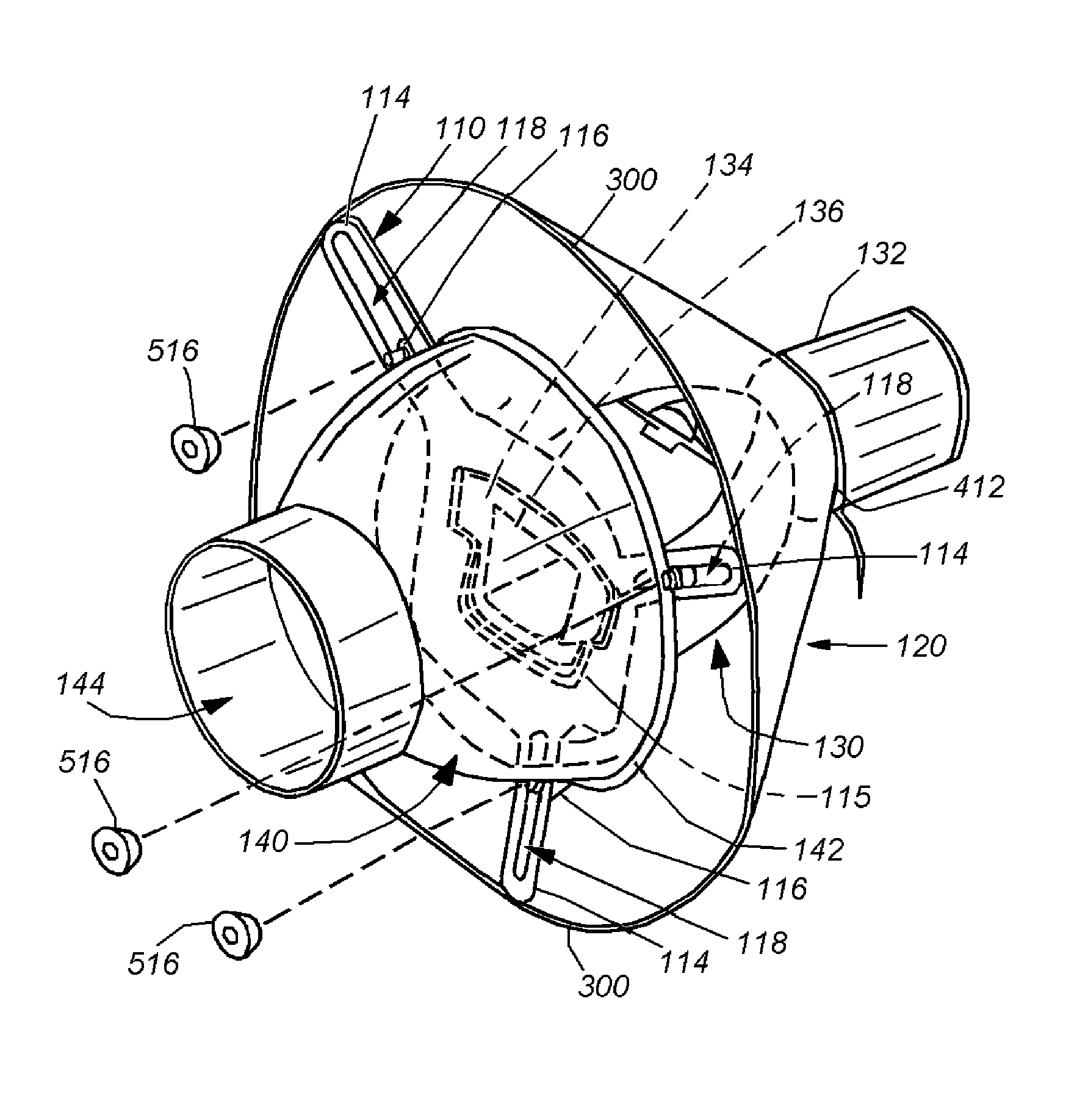
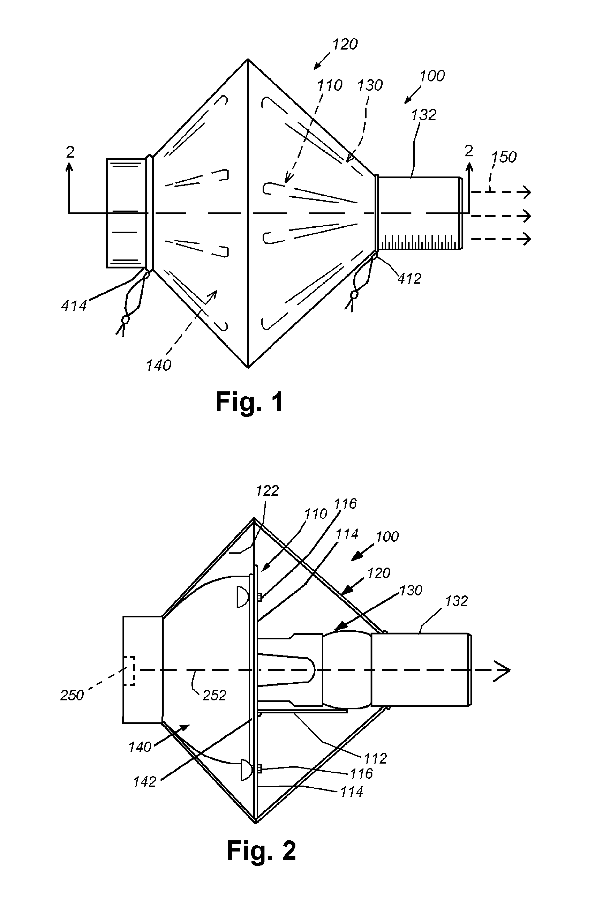
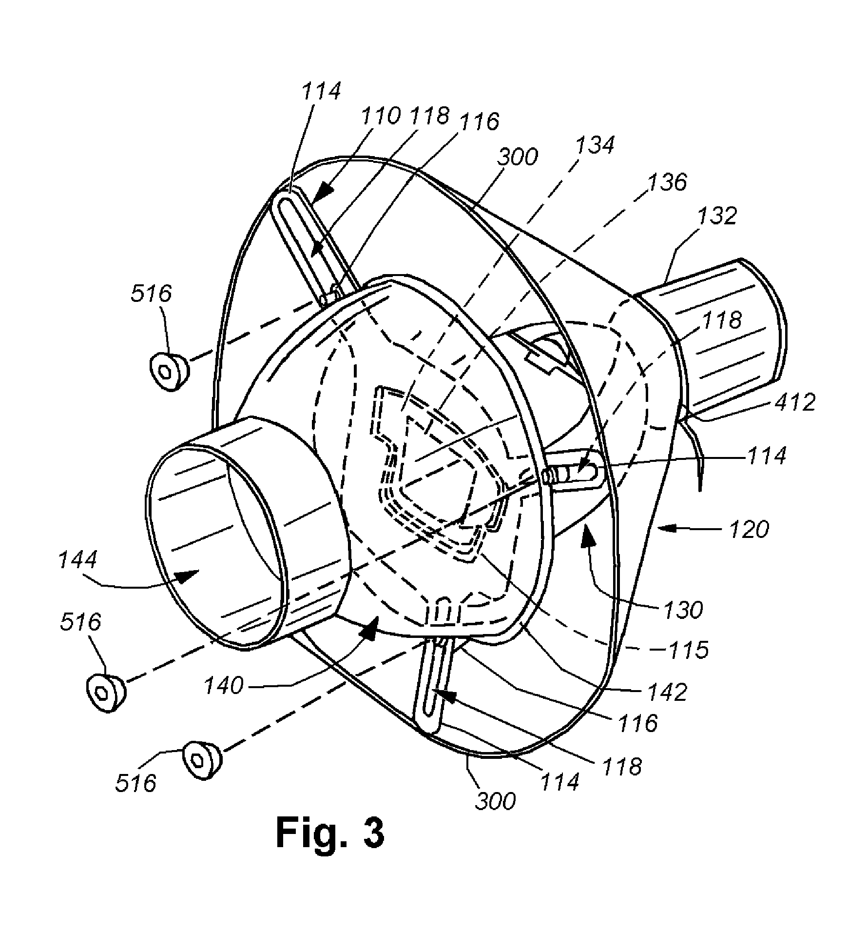
[0015]An illustrative universal adapter system for light-modifying devices is shown in FIGS. 1 and 2. With reference to FIG. 1, the system 100 is comprised of an adapter 110 (not shown, but described below), and a shrouding cone cover 120. The adapter 110 is a structural interface between an exemplary strobe light modifier light modifier 130 and a flash reflector 140. The exemplary strobe light modifier depicted is a light blaster that receives light from a light source and passes that light through an image slide for projection. In other embodiments, this light modifier can be a snoot, a ring light device, or another modifier. An exemplary light-modifying device in the form and function of a light blaster is shown and described in applicant's co-pending U.S. patent application Ser. No. 14 / 150,564, entitled SLIDE PROJECTOR HOUSING WITH MOUNT FOR DETACHABLE LENS AND STROBE, by Tirosh, the teachings of which are incorporated herein by reference as useful background information. The ad...


PUM


Abstract

An adapter that secures a light-modifying device and unites it with the light reflector and strobe light source that is readily adjustable and protected by a shroud. The adapter is comprised of an adapter body that is provided with a central aperture, a hinged connecting arm that is connected to the adapter body and is constructed with a through hole, a covering shroud that is constructed of opaque material and a plurality of arms that project outward from the adapter body. In an embodiment, the adapter is provided with three arms. Each adapter arm is provided with a moveable bolt and retaining nut that resides with a lateral slot therein. The connecting arm supports an engaged light-modifying device. The shroud is supported by a ring that engages the outer surface of each arm.

Description

FIELD OF THE INVENTION[0001]This invention relates to illumination devices and more particularly to illumination devices for photography that employ a strobe flash.BACKGROUND OF THE INVENTION[0002]Photographic cameras are sometimes aided with lighting coming from external sources. Those sources can be modified using accessories commonly known as “lighting modifiers”. Such lighting modifiers can use many types of lighting sources, but relevant types of light sources are of particular note: “hot shoe” strobes and “studio strobes”. Hot shoe strobes are small flashes which employ a standard triggering mechanism known as a hot shoe. They are typically small in size, powered by batteries, and relatively low in power. Studio strobes have bigger flashes, are usually powered off of the electric grid (or dedicated powerful batteries) and emit a very strong light pulse. Both types of strobes can accept lighting modifiers, including “softboxes”, “snoots”, and ring flashes.[0003]The connection b...

Claims


Application Information

Patent Timeline
Patent Type & Authority Patents(United States)
IPC IPC(8): G03B15/06F21V17/00G03B17/56
CPCG03B15/06G03B17/565F21V17/002F21V17/00G03B2215/0592
Inventor TIROSH, UDI JOSEF
Owner ORILI VENTURES
Learn More