
Image forming apparatus

a technology of image forming apparatus and forming tube, which is applied in the direction of electrographic process apparatus, instruments, optics, etc., can solve the problems of color misregistration, color misregistration, color misregistration, etc., and achieve the effect of suppressing color misregistration

Active Publication Date: 2016-09-20
CANON KK
View PDF14 Cites 1 Cited by
  • Summary
  • Abstract
  • Description
  • Claims
  • Application Information

AI Technical Summary

Benefits of technology

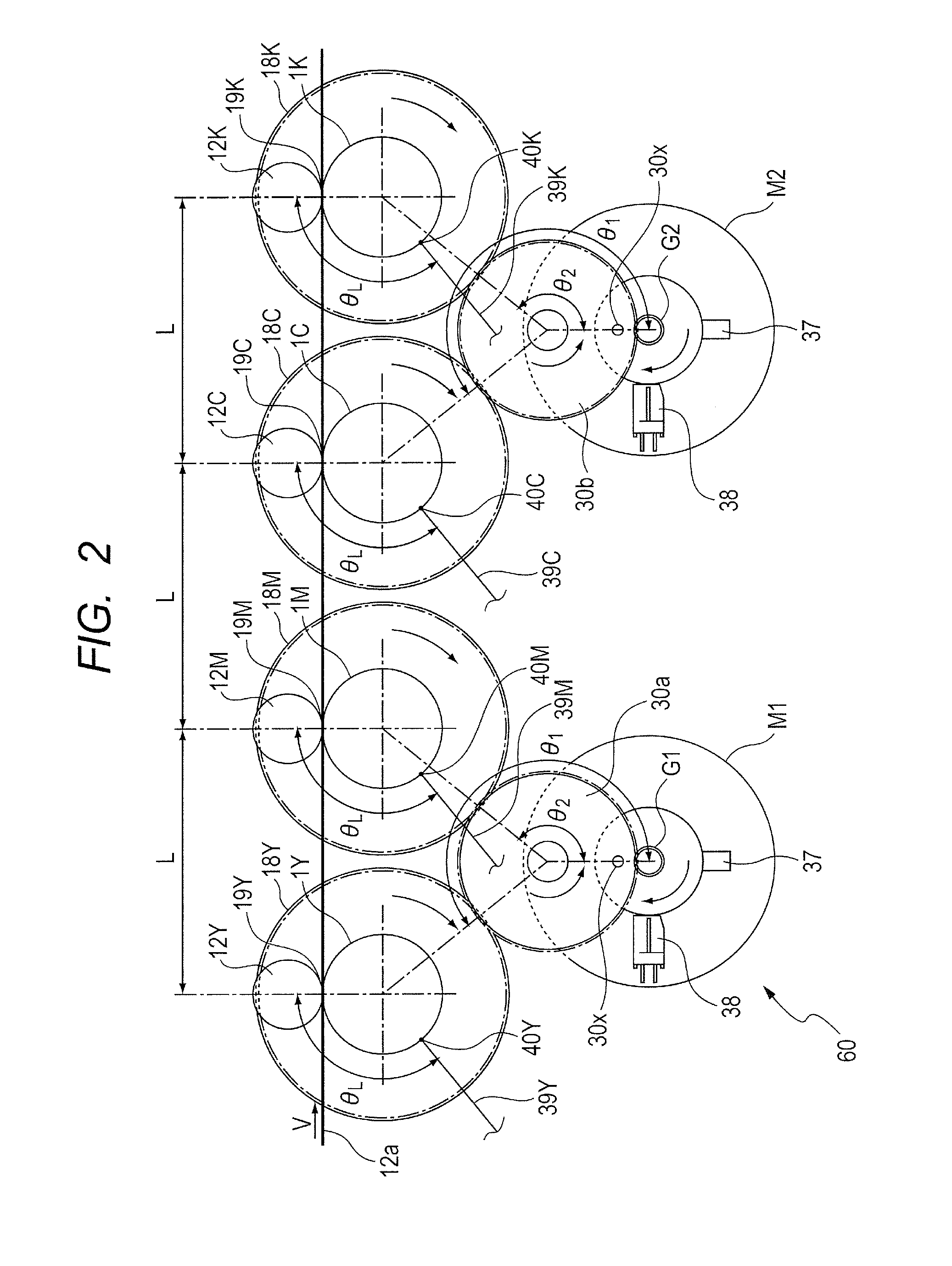
[0021]The present invention provides an image forming apparatus capable of optimizing all meshing angles of idler gears between drive gears and a transmission gear so as to suppress color misregistration.

Problems solved by technology

In this way, color misregistration may occur.
The regular color misregistration is caused by, for example, a failure in positioning during assembly of laser scanners of the respective colors.
This technology has a problem in that, in a case where the multiple photosensitive drums respectively have different meshing angles of the idler gears for transmitting a drive force to the photosensitive drums, rotational speeds of the photosensitive drums vary from each other at the same timing when transferring or exposing, resulting in the color misregistration.

Method used


Image

  • Image forming apparatus
  • Image forming apparatus
  • Image forming apparatus

Examples


first embodiment

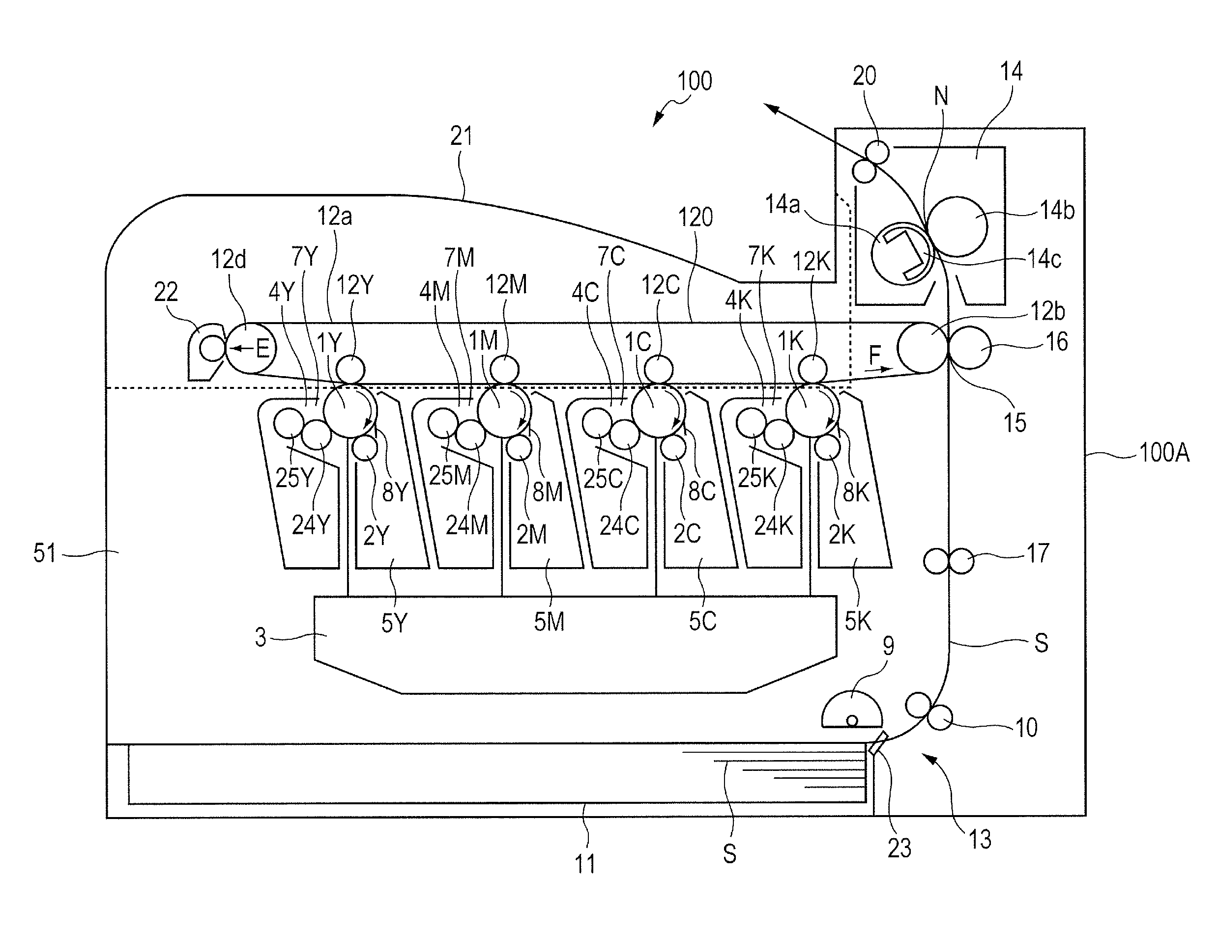
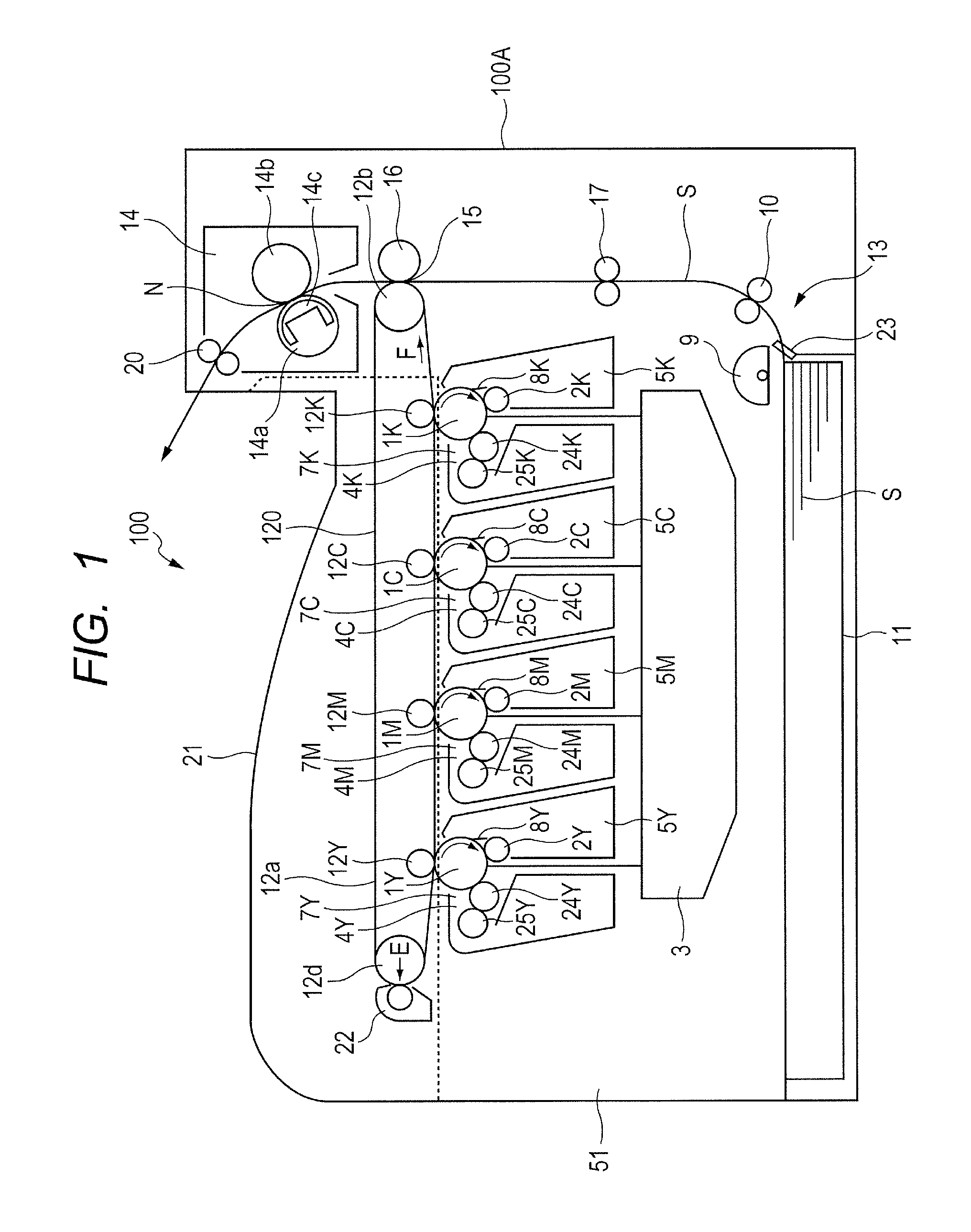
[0043]FIG. 1 is a sectional view of a configuration of an image forming apparatus 100 including a drive transmission device according to a first embodiment of the present invention. The image forming apparatus 100 is a color laser printer as a tandem type color image forming apparatus that utilizes an electrophotographic image forming process. As illustrated in FIG. 1, the image forming apparatus 100 includes an image forming apparatus main body (hereinafter simply referred to as “apparatus main body”) 100A, and an image forming portion 51 for forming images is provided inside the apparatus main body 100A. The image forming portion 51 includes photosensitive drums 1 as “image bearing members,” and primary transfer rollers 12 as “transfer devices.” At least the photosensitive drums 1 are contained in cartridges 7, and incorporated into the apparatus main body 100A through the cartridges 7.

[0044]The image forming apparatus 100 includes four photosensitive drums 1 (1Y, 1M, 1C, and 1K)....

second embodiment

[0097]FIG. 4 is a sectional view of a configuration of the primary transfer rollers 12, the photosensitive drums 1, a drive transmission device 260, and the primary transfer portion of an image forming apparatus according to a second embodiment of the present invention. The second embodiment is significantly different from the first embodiment in employing a drive transmission device of what is called a single motor system, that is, including one motor as the drive source. FIGS. 5A and 5B are graphs each illustrating rotational speed fluctuations of right-under idler gears 41 (41a and 41b).

[0098]The drive gears 18 (18Y, 18M, 18C, and 18K) are provided coaxially and integrally with the photosensitive drums 1 (1Y, 1M, 1C, and 1K) so as to transmit drive to the photosensitive drums 1. The motor M serves as a drive source, and the motor gear G is mounted integrally with the rotary shaft of the motor M. The right-under idler gears (41a and 41b) transmit drive to the branch gears 30 (30a ...


PUM


Abstract

Provided is an image forming apparatus, including first and second drive portions respectively transmitting a drive force to first and second photosensitive drums, the first and second drive portions each including: a transmission gear rotated by the drive force; an idler gear rotated in mesh with the transmission gear; and a drive gear rotated in mesh with the idler gear. When a meshing angle of the idler gear is an angle from a meshing position between the idler gear and the transmission gear to a meshing position between the idler gear and the drive gear with respect to a rotation center of the idler gear, the meshing angles of the idler gears of the first and second drive portions are substantially equal to each other, and rotational phases of the idler gears of the first and second drive portions match with each other.

Description

BACKGROUND OF THE INVENTION[0001]1. Field of the Invention[0002]The present invention relates to an image forming apparatus including a drive transmission device for driving a photosensitive drum and the like.[0003]2. Description of the Related Art[0004]Hitherto, as an electrophotographic image forming apparatus, a tandem type image forming apparatus for forming full color images has been provided. The tandem type image forming apparatus includes multiple image forming portions. Thus, depending on machine accuracy or the like, speed fluctuation or the like of multiple photosensitive drums and a transfer belt may occur unequally in respective colors, and images may be shifted when superimposing each other. In this way, color misregistration may occur.[0005]There are two types of color misregistration, that is, regular color misregistration and irregular color misregistration. The regular color misregistration is caused by, for example, a failure in positioning during assembly of lase...

Claims


Application Information

Patent Timeline
Patent Type & Authority Patents(United States)
IPC IPC(8): G03G15/00G03G21/18G03G15/01
CPCG03G15/757G03G15/0131G03G21/1857G03G2215/0132
Inventor INO, KAZUSHINAKASHIMA, SATOSHI
Owner CANON KK
Learn More