Supercharge Your Innovation With Domain-Expert AI Agents!

Communication system, communication method, node, and program for node

a communication system and communication method technology, applied in the field of communication systems, can solve problems such as the amount of traffic in the trunk communication system of the link connecting the network, and achieve the effect of extending the communication band between the networks and increasing the reliability of communication between the networks

Active Publication Date: 2016-10-04
NEC CORP
View PDF25 Cites 0 Cited by
  • Summary
  • Abstract
  • Description
  • Claims
  • Application Information

AI Technical Summary

Benefits of technology

The communication system described in this patent improves the reliability of communication between different networks and increases the bandwidth of the network communication. This is achieved by connecting nodes in one network with nodes in other networks using links.

Problems solved by technology

In particular, the traffic amount in a link connecting networks constructing the trunk communication system (herein below, described as “interlink”) is enormous.

Method used


Image

  • Communication system, communication method, node, and program for node
  • Communication system, communication method, node, and program for node
  • Communication system, communication method, node, and program for node

Examples


first embodiment

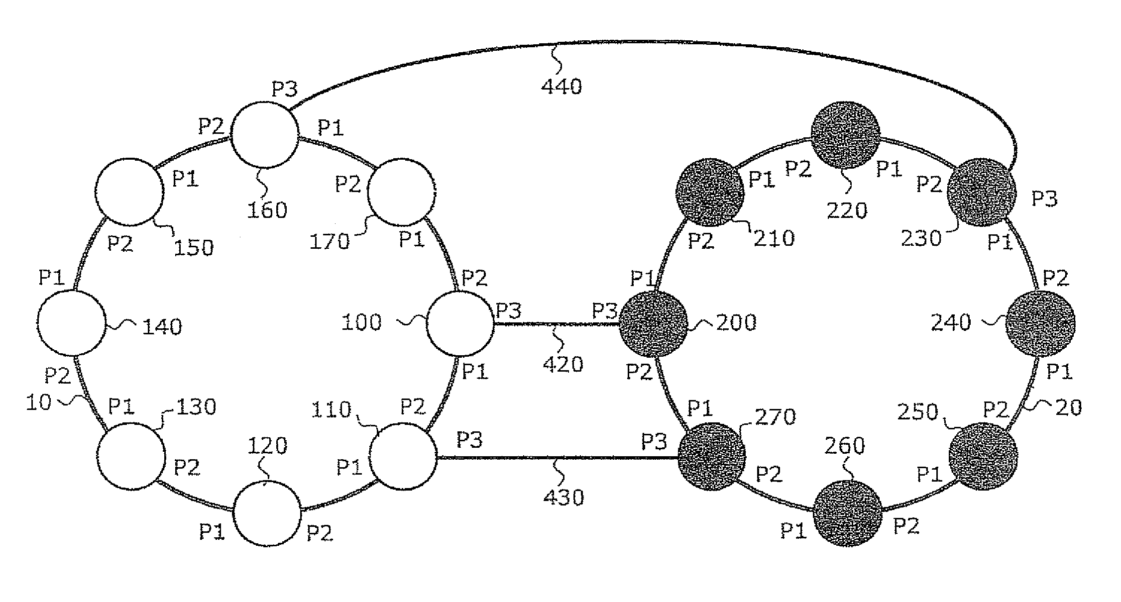
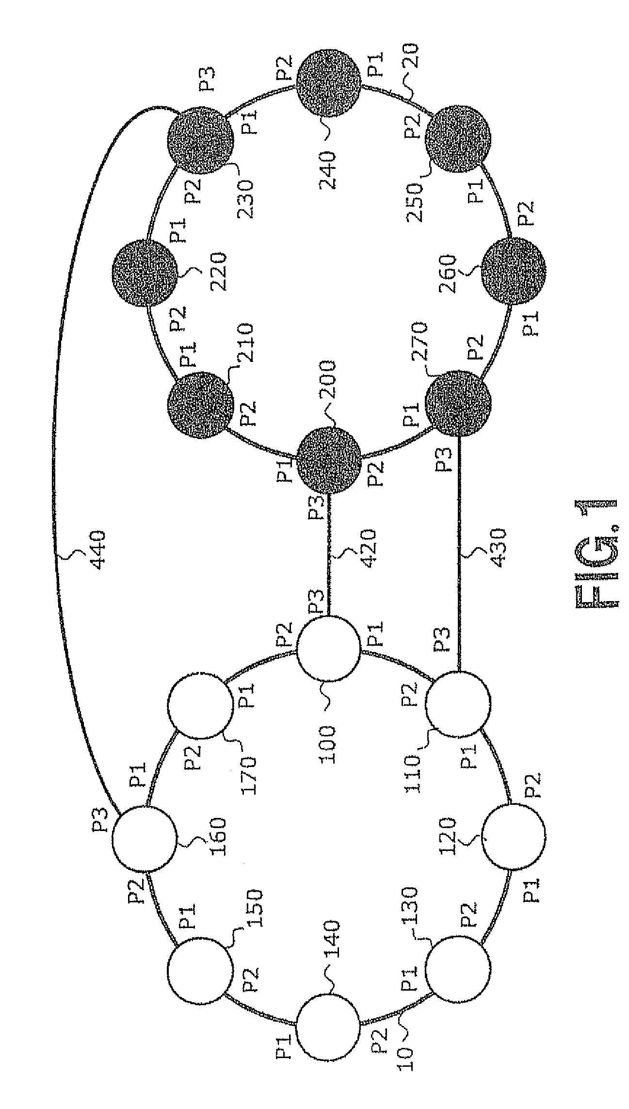
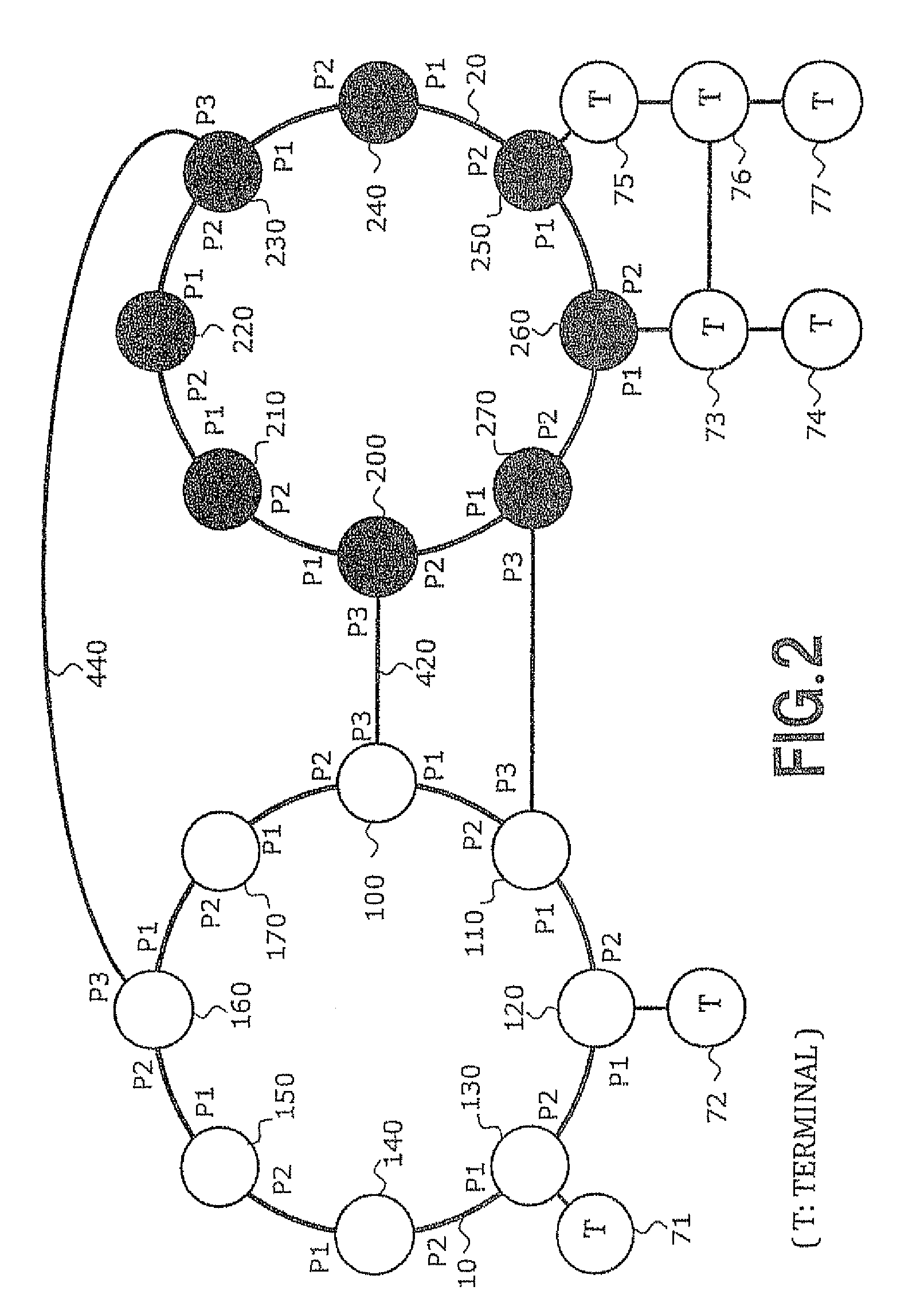
[0095]FIG. 1 is an explanatory diagram showing a first embodiment of a communication system according to the present invention. The communication system of the first embodiment has an RPR network 10 and an RPR network 20 each including RPR nodes. As described above, the RPR network is a network system to which the RPR is applied.

[0096]The RPR node is a node that operates in conformity with “IEEE Standards 802.17”. The RPR nodes of the communication system of the present invention (RPR nodes 100 to 170 and 200 to 270 in the example shown in FIG. 1) perform operation in conformity with “IEEE Standards 802.17” and also perform other operations (operations for realizing the objects of the present invention).

[0097]The RPR networks 10 and 20 are connected to each other via interlinks 420, 430, and 440. An interlink is a link connecting nodes in different networks (in the example, the networks 10 and 20) of the communication system.

[0098]Each of the RPR nodes of the first embodiment has th...

second embodiment

[0355]FIG. 15 is an explanatory diagram showing a second embodiment of a communication system according to the present invention. The same reference numerals as those of FIG. 1 are designated to components similar to those of the first embodiment and their description will not be repeated.

[0356]In the example shown in FIG. 15, the communication system includes an RPR network 10 having RPR nodes 100 to 170 and an EoE (Ethernet over Ethernet) network 30 having EoE nodes 700 to 770. The EoE nodes include an EoE edge node accommodating a terminal under the node, and an EoE core node for relaying an EoE frame without accommodating a terminal under the node. A terminal under the EoE edge node may be an RPR node belonging to an RPR network. In the example shown in FIG. 15, the RPR node 100 and the EoE node 700 are connected to each other via an interlink 450. The RPR node 110 and the EoE node 750 are connected to each other via an interlink 460. The RPR node 160 and the EoE node 720 are co...

third embodiment

[0384]FIG. 18 is an explanatory diagram showing a third embodiment of a communication system according to the embodiment. The RPR network 10 has the RPR nodes 100 to 170. In the example shown in FIG. 18, a common terminal 300 is accommodated under the RPR nodes 100, 110, and 170. Therefore, the RPR nodes 100, 110, and 170 are interlink connection nodes constructing an interlink connection node group. By such a configuration, the communication system shown in FIG. 18 realizes a multihoming configuration. Terminals 320, 330, 340, 350, and 360 are terminals accommodated under the RPR nodes 120, 130, 140, 150, and 160, respectively.

[0385]The configuration of each of the RPR nodes 100 to 170 is similar to that of each of the RPR nodes in the first embodiment (refer to FIG. 3).

[0386]The operations of the RPR nodes and the terminals in the third embodiment are similar to those of the first embodiment except for the following points. In the third embodiment, at the time of transmitting an E...


PUM


Abstract

In the case where a terminal under an RPR node (240) which does not belong to an interlink connection node group in an RPR network (20) transmits an Ethernet frame to a terminal under an RPR node of other RPR network (10), the RPR node (240) transmits an RPR frame in which the Ethernet frame is contained to any of interlink connection nodes (200, 230, and 270) in the same network. The interlink connection node which receives the RPR frame extracts the Ethernet frame from the RPR frame and transfers the extracted Ethernet frame to the other RPR network (10).

Description

TECHNICAL FIELD[0001]The present invention relates to a communication system, a communication method, a node, and a program for a node. More particularly, the invention relates to a reliable communication system, and a communication method, a node, and a program for a node applied to such a communication system.BACKGROUND ART[0002]In recent years, with spread of the Internet, the traffic amount of a trunk communication system increases rapidly. In particular, the traffic amount in a link connecting networks constructing the trunk communication system (herein below, described as “interlink”) is enormous. Therefore, to continuously provide stable communication, a high-reliable technique of suppressing occurrence of congestion caused by concentration of traffic and avoiding interruption of communication due to abnormality such as disconnection of an interlink, trouble in any of nodes at both ends of the interlink (herein below, called “interlink connection nodes”), and the like is extr...

Claims


Application Information

Patent Timeline
Patent Type & Authority Patents(United States)
IPC IPC(8): H04L12/46H04L12/413H04L12/42H04L29/12H04L12/24H04L12/437
CPCH04L12/4637H04L12/413H04L12/42H04L29/12584H04L29/12839H04L61/2596H04L61/6022H04L41/12H04L2101/622
Inventor OGASAHARA, DAISAKUSAKAUCHI, MASAHIRO
Owner NEC CORP
Features
  • R&D
  • Intellectual Property
  • Life Sciences
  • Materials
  • Tech Scout
  • Unparalleled Data Quality
  • Higher Quality Content
  • 60% Fewer Hallucinations
Learn More