Device for levelling and aligning surface covering parts

a technology for levelling and aligning parts, which is applied in the direction of flooring, building scaffolds, building aids, etc., can solve the problems of excessive length between successive holding points, excessive separation between parts, and the useless threaded parts of screws and/or wing nuts

Inactive Publication Date: 2016-11-01
TORRENTS RES
View PDF17 Cites 22 Cited by
  • Summary
  • Abstract
  • Description
  • Claims
  • Application Information

AI Technical Summary

Problems solved by technology

The device in this patent has a number of drawbacks, notably that the threaded parts of the screw and / or wing nut may be rendered useless if they come into contact with the mortar or fixing material for the covering parts, and the excessively large separation between said parts because of the thickness of the screw, especially when the parts to be used are of small dimensions.
The lock incorporated in the locking plate is coupled to the stem using complementary gear teeth of sizeable dimensions, which means that there is an excessive length between the successive holding points and that the alignment and levelling of the parts forming the covering is not sufficiently precise.
As in the previous case, these inventions do not allow progressive insertion and appropriate adjustment of the top plate during the levelling of the parts which form the covering.
This invention, like the previous ones, has the disadvantage that each device is positioned individually, which makes alignment and levelling of covering parts difficult, especially when they are of longer length.
Another drawback in use comes from the fact that a large number of individual, independent devices must be used for the alignment and levelling of the covering parts.
Another drawback of this device is determined precisely by the flat configuration of the lower body, which prevents the covering parts from being gripped correctly in the cement or fixing medium with regard to the surface to be covered.

Method used


Image

  • Device for levelling and aligning surface covering parts
  • Device for levelling and aligning surface covering parts
  • Device for levelling and aligning surface covering parts

Examples


first embodiment

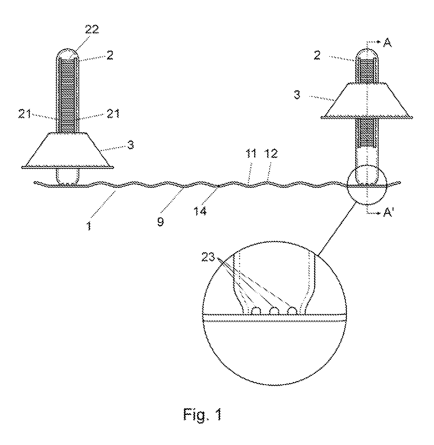
[0047]In a first embodiment, and as can be seen in the attached FIGS. 1 to 4, the device in the invention comprises a first rectangular base (1) with a longitudinal structure.

second embodiment

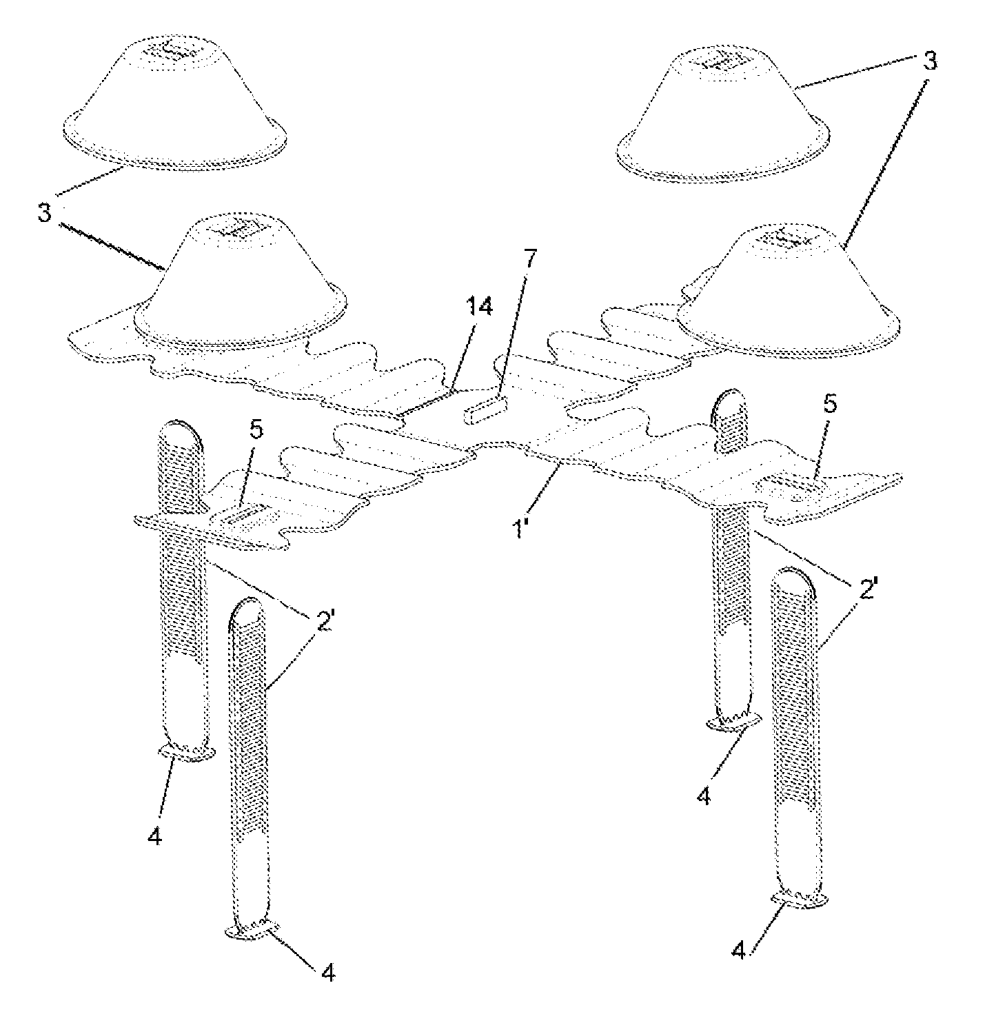
[0048]In a second embodiment, and as presented in FIGS. 5 to 15, the device in the invention comprises a second base (1′). This second base (1′) is rectangular with a longitudinal structure or with a structure in the form of an orthogonal cross, in which the base (1′) has two or four ends (8), respectively.

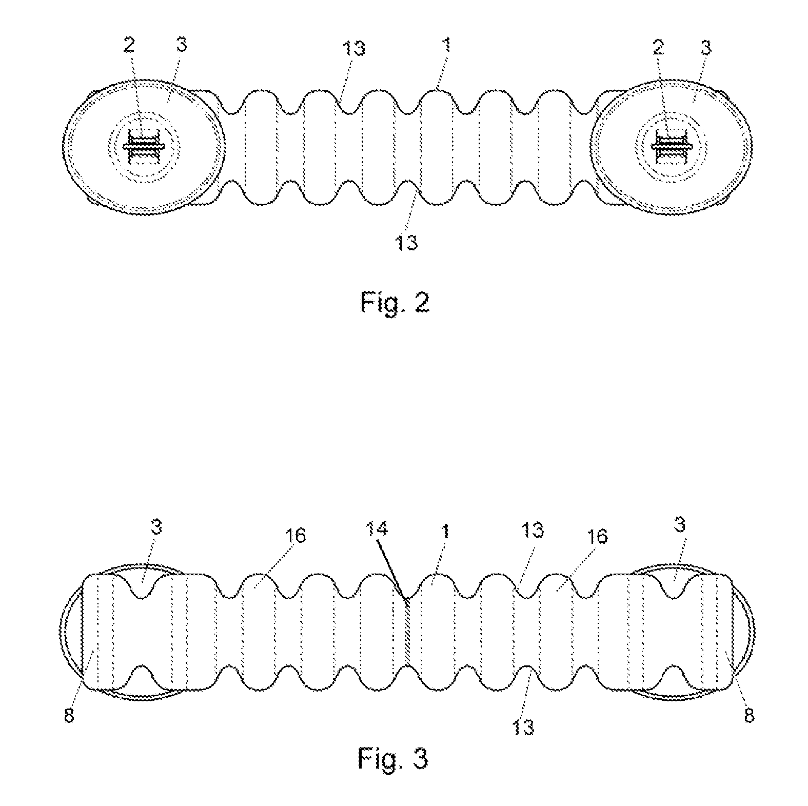
[0049]The bases (1, 1′) have a longitudinal section with an undulated structure (9) which defines a series of troughs (11) and peaks (12) alternating along its length. In addition, the rectangular form of the longitudinal bases (1, 1′) and of the arms (15) of the cross-shaped base (1′) has an undulated configuration (13) on the longer sides, as represented, amongst others, in FIGS. 2 and 3.

[0050]The bases (1, 1′) incorporate at least two flexible planar attachments (2, 2′), arranged to coincide with a longitudinal middle plane on the bases (1, 1′). The flexible attachments (2, 2′) are arranged symmetrically on the bases (1, 1′) along their length, with two of these attachments clo...

third embodiment

[0063]In a third embodiment, the device has more than three flexible attachments (2′). The base (1″) is formed of a surface with an undulated structure (9) which comprises a series of perforations (17) positioned crosswise to the base (1″) on both sides of each rectangular drill-hole (6). The perforations (17) facilitate the penetration of the cement or fixing medium for the covering parts (P) and the levelling thereof when pressed from above by the upper bodies (3) of the device. The base (1″) in this embodiment has a surface with an undulated structure (9) in a perpendicular direction to that used in the previous embodiments, so that it can be manufactured by extrusion. Both the rectangular drill-holes (6) and the perforations (17) are created at a later stage of manufacture. An example is shown in FIG. 16, which is especially suitable for situations in which covering parts (P) of a large size are used, for example parts measuring 2 m by 1 m.

[0064]In all the embodiments, the devic...


PUM


Abstract

A device used in the installation of a surface of ceramic parts that are levelled and aligned using a securing product. The device includes: a base, with an orthogonal cross-shaped structure formed of four arms, having an undulating surface; and at least two flexible planar attachments projecting up from the base and positioned symmetrically along the length of the base. The opposing planar surfaces of each of the flexible attachments including side ribs for slidably mounting and guiding upper bodies which, by applying pressure, contact with the upper surface of multiple covering parts (P), thereby being levelled.

Description

BACKGROUND OF THE INVENTION[0001]1. Technical Field[0002]This invention relates to a device for levelling and aligning surface covering parts, appropriate to install a surface of ceramic parts or similar that are suitably levelled and aligned.[0003]The invention is applicable in the field of construction and refurbishment, particularly in the application of surface covering tiles or parts.[0004]2. Description of the Related Art[0005]There currently exist in the market different devices designed to facilitate the levelling and alignment of surface covering parts using a layer of mortar, glue cement or other suitable adhesive for securing them to the surface in question.[0006]The purpose of these known devices is to facilitate the correct positioning of the parts forming the covering, so that the covering defines a flat, levelled surface, and the parts in question are kept at uniform distance apart.[0007]A known device is described in the U.S. Pat. No. 4,397,125, which has a rear plat...

Claims


Application Information

Patent Timeline
Patent Type & Authority Patents(United States)
IPC IPC(8): E04B2/82E04F21/00E04G1/22E04B9/00E04F21/22E04F21/20E04F15/02E04F21/18
CPCE04F21/0092E04F21/1877E04F21/22E04F15/02005E04F15/02027E04F15/02033E04F21/1894E04F21/20
Inventor TORRENTS I COMAS, JOSEP
Owner TORRENTS RES
Why Eureka
Try Eureka