
Slide bar anchorage device for aerial lift equipment

a technology of lifting equipment and sliding bars, which is applied in the direction of lifting devices, safety devices for lifting equipment, safety belts, etc., can solve the problems of limiting the ability of workers to move around on the aerial lift and perform work, and the six-foot lanyard is not likely to be able to stop the workers falling before the workers

Active Publication Date: 2016-11-15
BYRD MICHAEL
View PDF25 Cites 13 Cited by
  • Summary
  • Abstract
  • Description
  • Claims
  • Application Information

AI Technical Summary

Benefits of technology

The patent is about a new system for safety on aerial lifts. If a shorter lanyard is used, it limits a workers ability to move around and perform work. The new system allows for more ease and comfort while also meeting safety regulations. A removable anchorage device can be used with a supplementary lanyard and the mounting bars can be hollow to allow for the lanyard to pass through. This prevents the anchorage device from falling off the aerial lift when the supplementary lanyard is attached. Overall, this new system makes it safer and more comfortable to work at heights.

Problems solved by technology

When the worker is raising the bucket out of its cradle and working over the top of elevated obstructions, including the bed of the aerial lift truck, the six-foot lanyard is not likely to be able to stop the workers fall before the worker contacts a lower level obstruction.
If a shorter lanyard is used, the current factory-installed anchorage points will limit a worker's ability to move around on the aerial lift and perform work.

Method used


Image

  • Slide bar anchorage device for aerial lift equipment
  • Slide bar anchorage device for aerial lift equipment
  • Slide bar anchorage device for aerial lift equipment

Examples


Embodiment Construction

[0028]For the purposes of promoting an understanding of the principles of the novel invention, reference will now be made to the embodiments described herein and illustrated in the drawings and specific language will be used to describe the same. It will nevertheless be understood that no limitation of the scope of the novel invention is thereby intended, such alterations and further modifications in the illustrated devices and methods, and such further applications of the principles of the novel invention as illustrated therein being contemplated as would normally occur to one skilled in the art to which the novel invention relates.

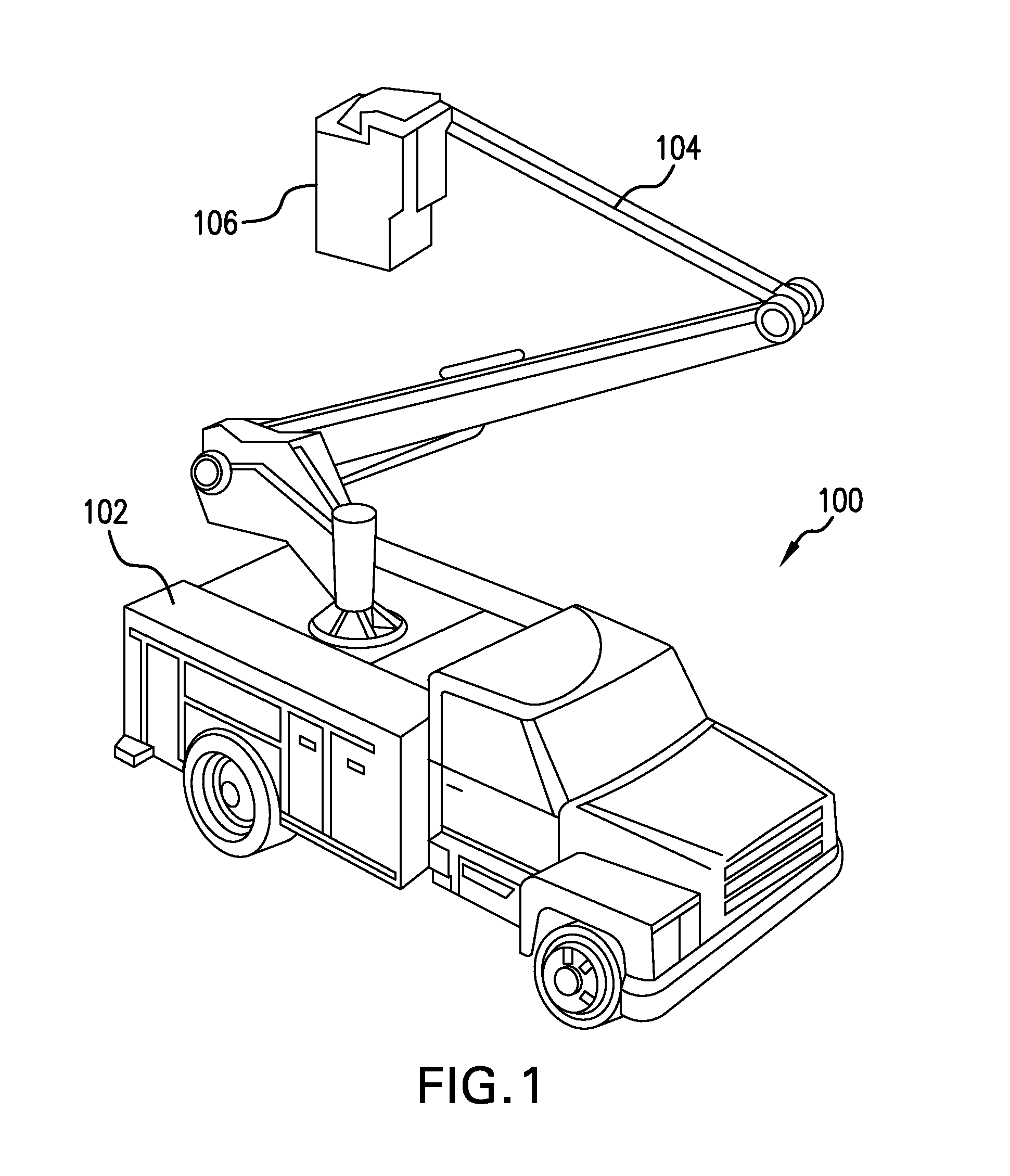
[0029]FIG. 1 illustrates an exemplary aerial lift vehicle which in this case is a bucket truck 100. The bucket truck 100 includes a truck bed 102, an aerial lift boom 104 and a bucket 106. One end of the aerial lift boom 104 is coupled to the truck bed 102 and the opposite end of the aerial lift boom 104 is coupled to the bucket 106. When the boom 104 is...


PUM


Abstract

Anchorage devices for an aerial lift that can include a base plate and a slide bar coupled to the base plate. The aerial device can include a bucket, and the base plate can be coupled to the inside or outside of the bucket. Supplementary anchorage points of the anchorage device can be attached to the lift using lanyards. The slide bar can be attached to the base plate using stanchions. A removable anchorage device can include inner and outer mounting bars, bucket engaging brackets coupling the mounting bars, and a slide bar; where the bucket engaging brackets fit over the bucket for attachment to and detachment from the bucket. The removable anchorage device can include supplementary anchorage points for attaching to the lift using lanyards. One of the mounting bars can be hollow and a supplementary lanyard attached to the lift can pass through the hollow mounting bar.

Description

[0001]This application claims priority to U.S. Provisional Patent Application Ser. No. 62 / 029,236, filed Jul. 25, 2014 entitled “Personal Fall Protection / Restraint Device for Aerial Lift Equipment and Bucket Trucks for Worker Protection with Two Options ‘Slide Bar Anchorage Device’ and ‘Inside Slide Bar Anchorage Device’”, the disclosure of which is expressly incorporated herein by reference.BACKGROUND AND SUMMARY[0002]The present invention generally relates to fall protection / restraint devices, and more specifically to personal fall protection / restraint devices for worker protection while working in bucket trucks or other aerial lift equipment.[0003]Effective Apr. 15, 2015, according to the Occupational Safety and Health Administration (OSHA) Standard 29 C.F.R. §1926.502(d)(16)(iii), personal fall arrest systems when stopping a fall from an aerial lift shall “be rigged such that an employee can neither free fall more than 6 feet (1.8 m), nor contact any lower level” if ejected from...

Claims


Application Information

Patent Timeline
Patent Type & Authority Patents(United States)
IPC IPC(8): A62B35/00B66F17/00
CPCA62B35/0068A62B35/0081B66F17/006
Inventor BYRD, MICHAEL
Owner BYRD MICHAEL
Learn More