Shift register unit, gate driving circuit, and display device

a technology of shift register unit and gate driving circuit, applied in the field of display technology, can solve problems such as affecting achieve the effects of improving the stability of the shift register unit, reducing the time over which a device is at a turn-on level, and reducing the probability of generating a threshold voltage dri

Active Publication Date: 2016-12-27
BOE TECH GRP CO LTD +1
View PDF11 Cites 1 Cited by
  • Summary
  • Abstract
  • Description
  • Claims
  • Application Information

AI Technical Summary

Benefits of technology

[0004]An object of the present invention is to provide a shift register unit, a gate driving circuit and a display device, which can reduce a probability of generating a threshold voltage drift for a device, thus improving stability of a shift register unit.
[0022]In the shift register unit, the gate driving circuit and the display device provided by the present invention, each shift register unit only includes one clock signal, and it, compared to a traditional shift register unit including two clock signals, reduces time over which a device is at a turn-on level, and lowers a probability of generating a threshold voltage drift for the device, thus improving stability of the shift register unit. In addition, the shift register unit in the embodiments only comprises four control signals, which can reduce wiring space.

Problems solved by technology

However, a traditional shift register unit generally includes two clock signals opposite in phase, in which a turn-on level occupies a relatively long time, and therefore, a threshold voltage drift may occur in a TFT receiving the clock signals after long hours of operation, thus impacting stability of a shift register unit.

Method used


Image

  • Shift register unit, gate driving circuit, and display device
  • Shift register unit, gate driving circuit, and display device
  • Shift register unit, gate driving circuit, and display device

Examples


Embodiment Construction

[0032]Technical solutions in embodiments of the present invention will be described clearly and completely below in conjunction with the accompanying drawings, and the embodiments to be described are merely a part but not all of the embodiments of the present invention. All other embodiments which, based on the embodiments of the present invention, are obtained by those skilled in the art without creative efforts belong to the protection scope of the present invention.

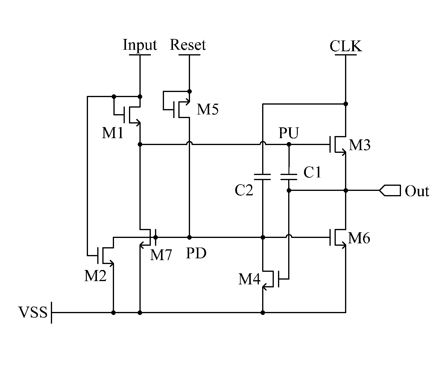
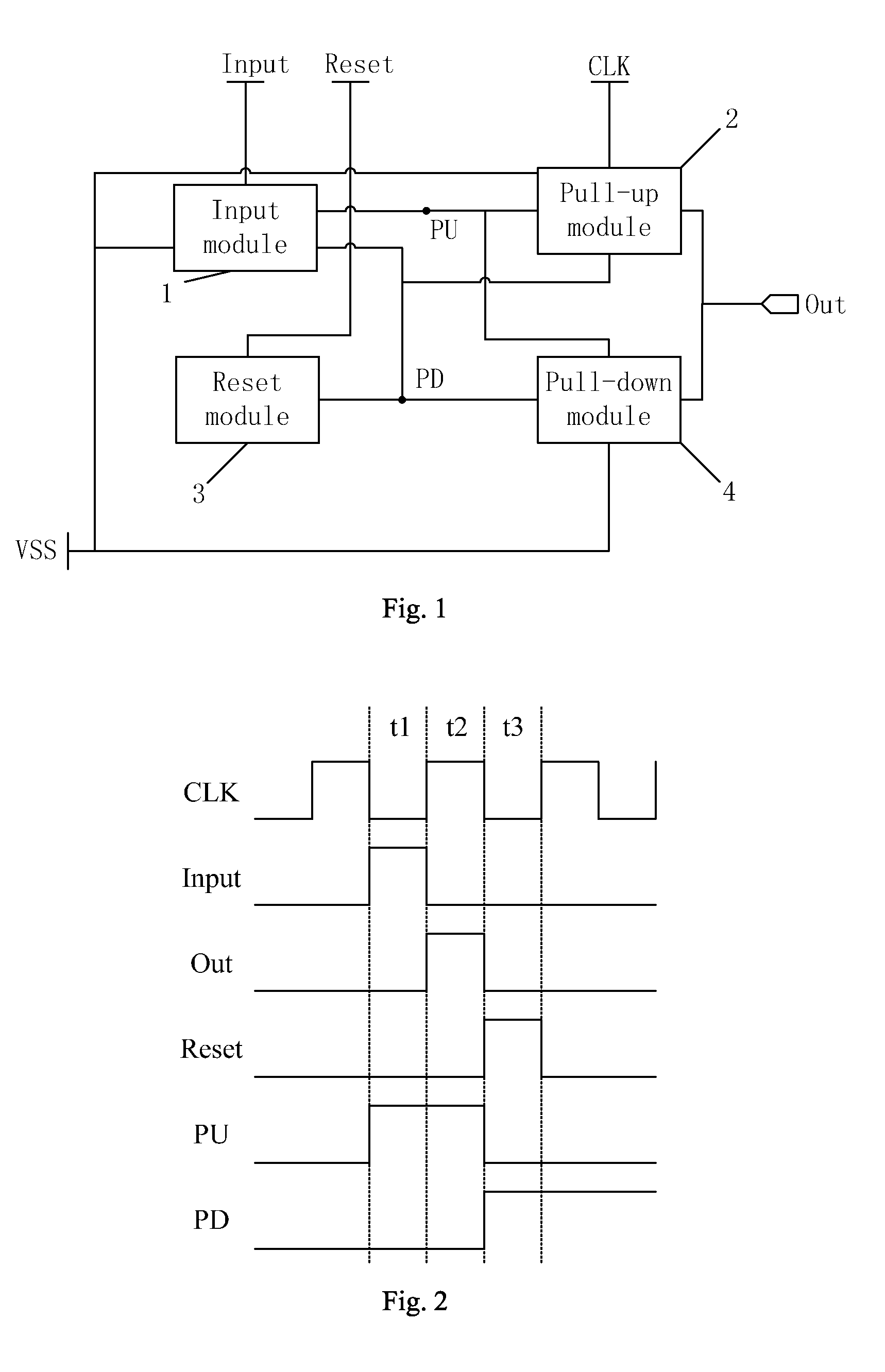
[0033]As shown in FIG. 1, the embodiments of the present invention provide a shift register unit, comprising: an input module 1 connected to a shift register input terminal Input, a first node PU, a second node PD and a turn-off level input terminal VSS, the input module 1 being used for, in response to a turn-on level (that is, a shift register input signal) input via the shift register input terminal Input, providing the turn-on level input via the shift register input terminal Input to the first node PU, and providi...


PUM


Abstract

The present invention provides a shift register unit, a gate driving circuit and a display device. The shift register unit comprises: an input module for, in response to turn-on level input via the shift register input terminal, providing turn-on level to the first node and providing turn-off level to the second node; a pull-up module for, in response to turn-on level of the first node, providing a clock signal to the shift register output terminal, and also used for, in response to turn-on level output by the shift register output terminal, providing turn-off level to the second node; a reset module for, in response to turn-on level input via the reset signal input terminal, providing the turn-on level to the second node; and a pull-down module for, in response to turn-on level of the second node, providing turn-off level to the shift register output terminal and the first node.

Description

FIELD OF THE INVENTION[0001]The present invention relates to the field of display technology, and in particular to a shift register unit, a gate driving circuit, and a display device.BACKGROUND OF THE INVENTION[0002]In a traditional display, in general, an external driving chip is used to drive pixels on a display panel to display a picture. However, to reduce the amount of elements and lower manufacturing cost, currently, a technique of manufacturing a structure of a driving circuit directly on a display panel has been gradually adopted, for example, a technique of Gate On Array (GOA). In a display panel adopting a GOA technique, a gate driving circuit comprising multiple stages of shift register units is used to provide scanning signals.[0003]However, a traditional shift register unit generally includes two clock signals opposite in phase, in which a turn-on level occupies a relatively long time, and therefore, a threshold voltage drift may occur in a TFT receiving the clock signa...

Claims


Application Information

Patent Timeline
Patent Type & Authority Patents(United States)
IPC IPC(8): G11C19/00G11C19/28G11C19/18
CPCG11C19/28G11C19/184G09G2310/0267G09G2310/0286
Inventor MA, LEI
Owner BOE TECH GRP CO LTD
Why Eureka
Try Eureka