
Optical-to-electrical converter and analog-to-digital converter thereof

an optical-to-electrical converter and analog-to-digital converter technology, applied in the field of analog-to-digital converters thereof, can solve the problem of threshold voltage drift of transistors along the operation time, and achieve the effect of reducing the affect of threshold voltage drift on the comparator

Active Publication Date: 2010-02-09
AU OPTRONICS CORP
View PDF8 Cites 2 Cited by
  • Summary
  • Abstract
  • Description
  • Claims
  • Application Information

AI Technical Summary

Benefits of technology

[0009]Accordingly, the present invention is directed to an analog-to-digital converter (ADC), wherein transistor threshold voltage drift in the comparators is reduced and the power consumption of the comparators is also reduced.
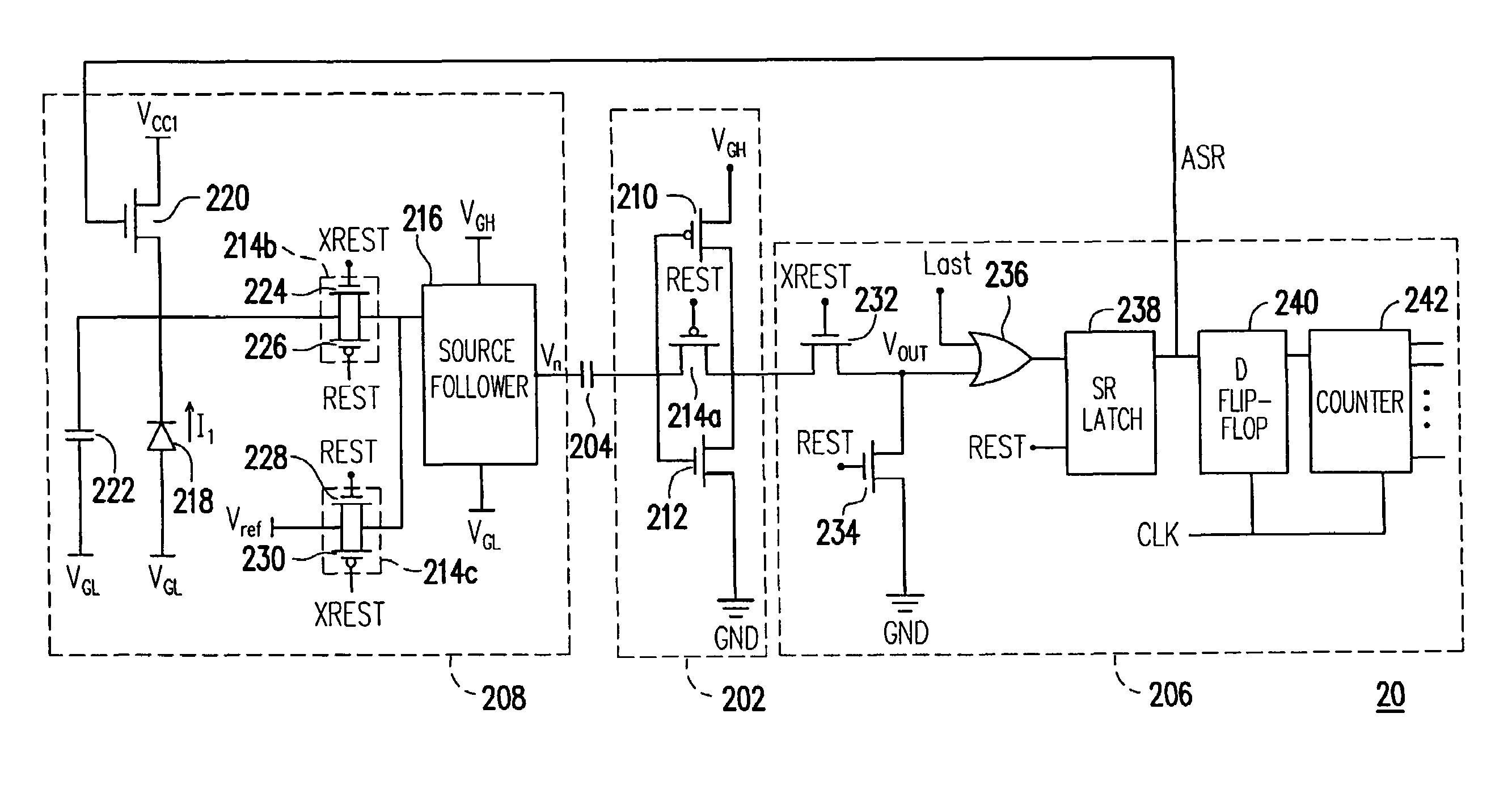
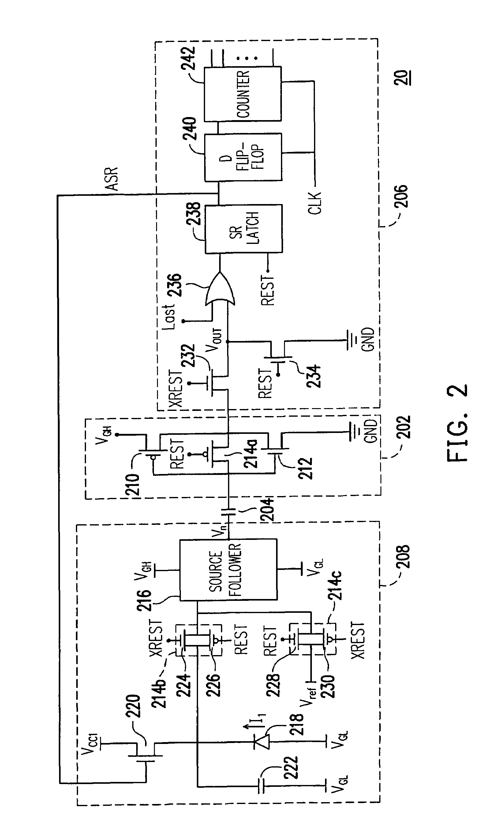
[0019]In an ADC provided by the present invention, a first switch unit is disposed in the inverter formed by a PMOS transistor and an NMOS transistor. The first switch unit is disposed between the input terminal and the output terminal of the inverter. When the first switch unit is turned on, the voltage levels at the input terminal and the output terminal of the inverter are the same such that a straight line having a slope of 45° is formed in the electrical characteristic graph of the inverter and this straight line intersects the electrical characteristic curve of the inverter at a particular point. The voltage value at this point will not drift along the operation time of the inverter, thus, the affection caused by threshold voltage drift to the comparators can be reduced.

Problems solved by technology

However, if these transistors are fabricated through low temperature poly-silicon processes, the threshold voltages of the transistors will drift along the operation time thereof.

Method used


Image

  • Optical-to-electrical converter and analog-to-digital converter thereof
  • Optical-to-electrical converter and analog-to-digital converter thereof
  • Optical-to-electrical converter and analog-to-digital converter thereof

Examples


Embodiment Construction

[0026]Reference will now be made in detail to the present preferred embodiments of the invention, examples of which are illustrated in the accompanying drawings. Wherever possible, the same reference numbers are used in the drawings and the description to refer to the same or like parts.

[0027]FIG. 2 is a circuit block diagram of an analog-to-digital converter (ADC) 20 according to an embodiment of the present invention. Referring to FIG. 2, the ADC 20 may be an optical-to-electrical converter which includes an inverter 202, a capacitor 204, a detection module 208, and an output module 206. The input terminal of the inverter 202 is coupled to the output terminal of the detection module 208 through the capacitor 204, and the output terminal of the inverter 202 is coupled to the input terminal of the output module 206. The output module 206 further issues an asynchronous latch signal ASR to the detection module 208.

[0028]In the present embodiment, the inverter 202 includes a PMOS trans...


PUM


Abstract

An analog-to-digital converter (ADC) for converting an optical signal into an electrical signal is disclosed. The ADC includes a detection module, a first P-type metal oxide semiconductor (PMOS) transistor, a first N-type metal oxide semiconductor (NMOS) transistor, a first switch unit, and an output module. The first PMOS transistor and the first NMOS transistor form an inverter. The first switch unit is disposed between the input terminal and the output terminal of the inverter and is turned on / off according to a first control signal. The output module is coupled to the output terminal of the inverter for counting the time that an input voltage is greater than a reference voltage and generating a digital signal.

Description

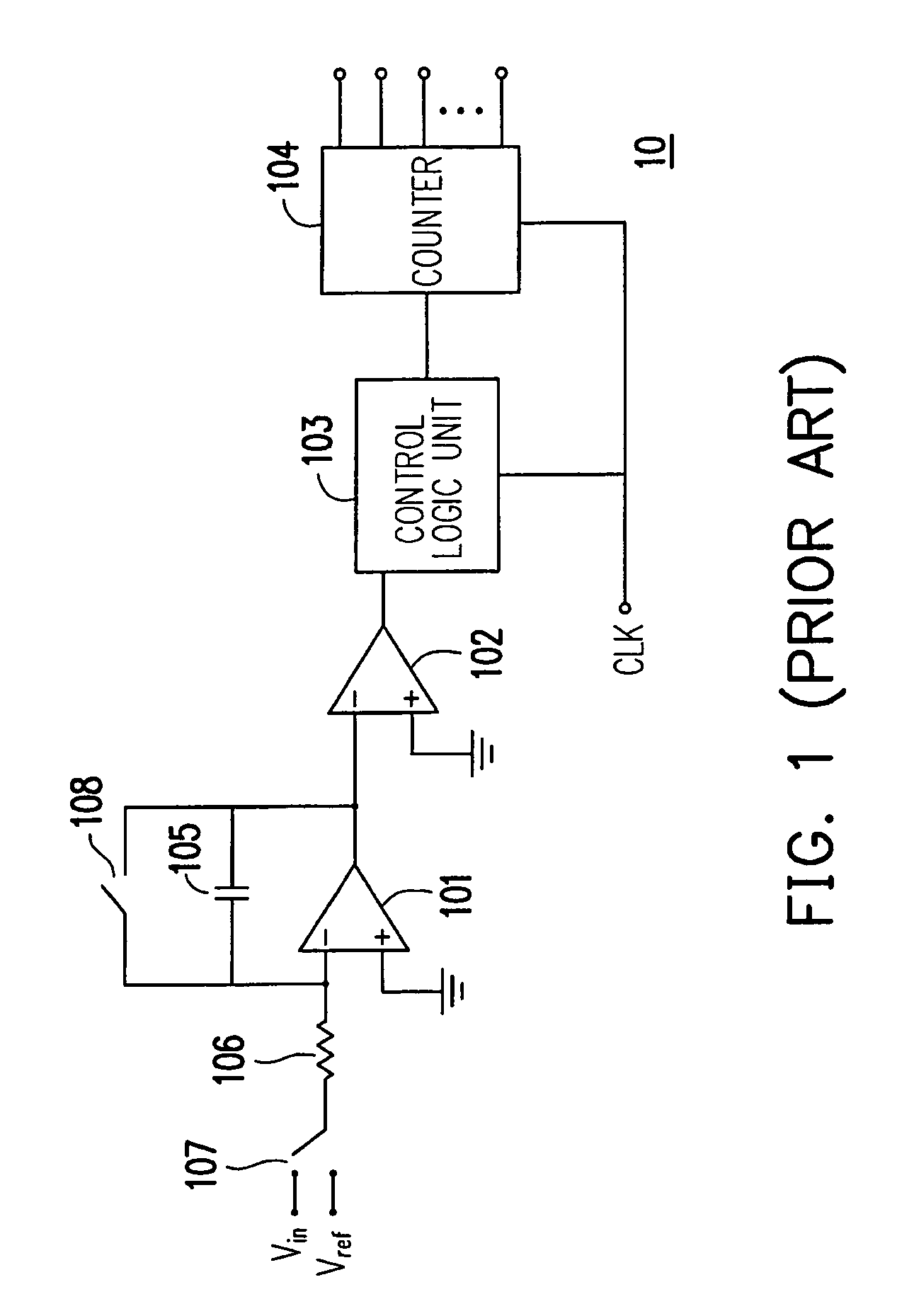
CROSS-REFERENCE TO RELATED APPLICATION[0001]This application claims the priority benefit of Taiwan application serial no. 96127474, filed on Jul. 27, 2007. The entirety of the above-mentioned patent application is hereby incorporated by reference herein and made a part of this specification.BACKGROUND OF THE INVENTION[0002]1. Field of the Invention[0003]The present invention relates to an analog-to-digital converter (ADC), and in particular, to an ADC for converting an optical signal into an electrical signal.[0004]2. Description of Related Art[0005]FIG. 1 is a circuit block diagram of a conventional analog-to-digital converter (ADC). Referring to FIG. 1, the conventional ADC 10 includes two comparators 101 and 102, a control logic unit 103, a counter 104, a capacitor 105, a resistor 106, and two switch units 108 and 107. One terminal of the switch unit 107 is selectively coupled to an input voltage Vin or a reference voltage Vref, and the other terminal thereof is coupled to the ne...

Claims


Application Information

Patent Timeline
Patent Type & Authority Patents(United States)
IPC IPC(8): H03M1/56
CPCH03M1/54
Inventor TSENG, HUNG-WEIHU, LING-CHANGLU, SHI-HSIANGSUN, WEIN-TOWN
Owner AU OPTRONICS CORP
Learn More