
Device for resisting lifting of a gangway and gangway fitted with such device

a technology for lifting cylinders and gangways, which is applied in the direction of bridges, bridge construction, construction, etc., can solve the problems of inadvertent deactivation, increased cost of actuating cylinders, and increased complexity and expens

Active Publication Date: 2017-01-17
SAM CARBIS ASSET MANAGEMENT
View PDF15 Cites 1 Cited by
  • Summary
  • Abstract
  • Description
  • Claims
  • Application Information

AI Technical Summary

Benefits of technology

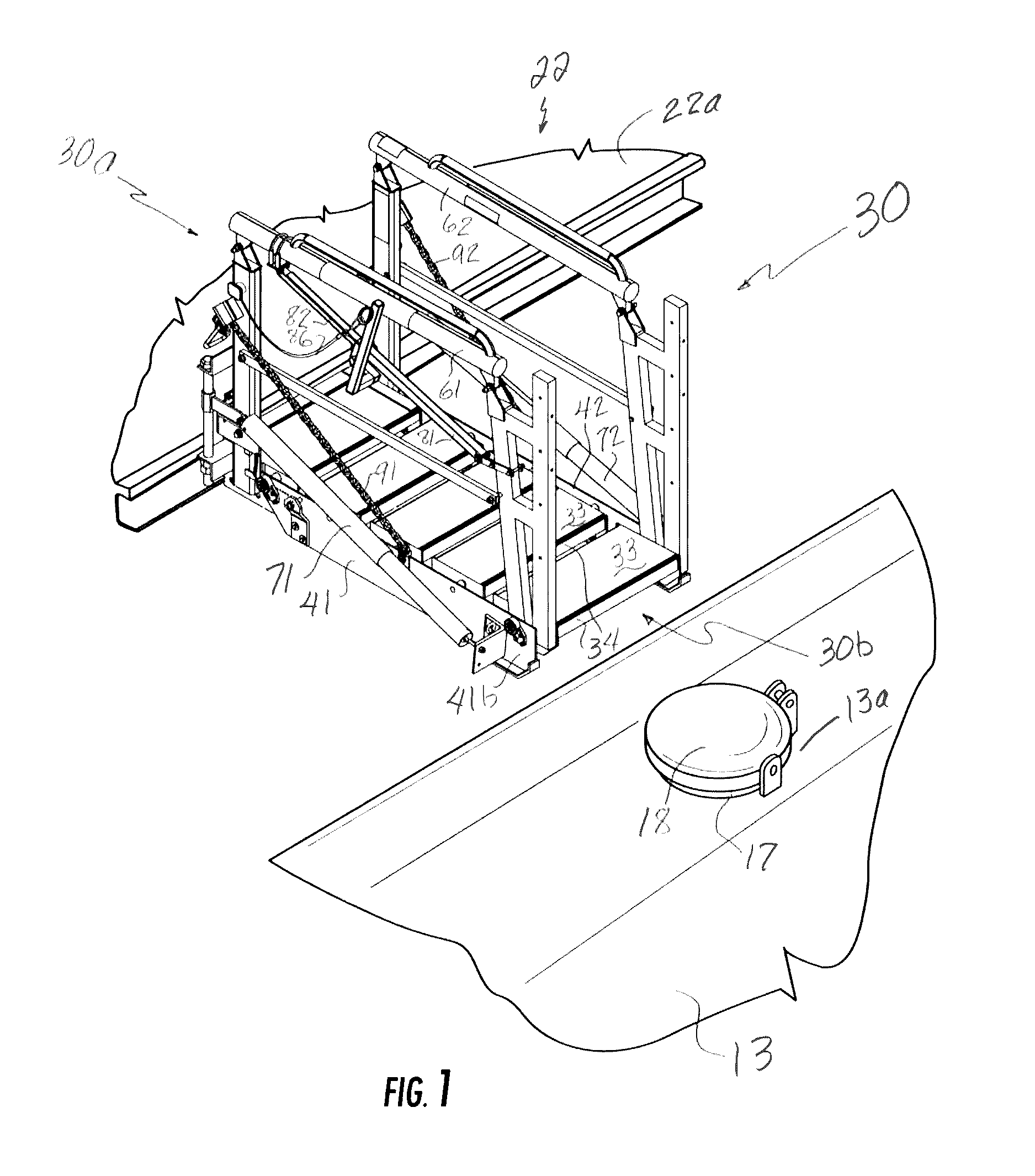
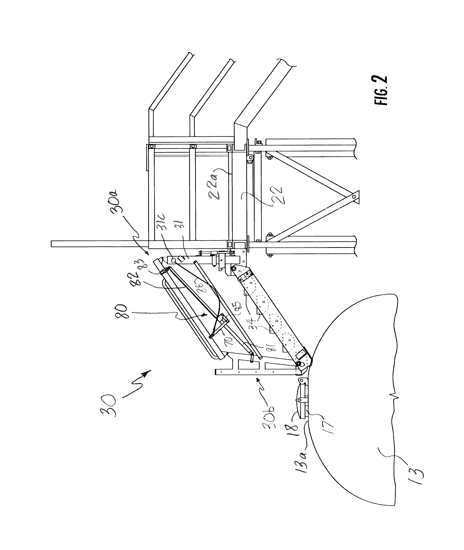
The present invention is about a new type of sprung gangway for accessing the tops of rolling stock, which is a type of fall protection equipment. The invention is a continuation-in-part of a previous patent application, and it is designed to improve safety for workers who need to access the top of a tank or railcar. The invention includes a retractable stairway that can be stored in a position above the platform where it is attached, and it can be moved between a lowered and an elevated position. The invention also includes a foot-activated lock to secure the gangway in the lowered position, but there is a risk of accidental deactivation or exposing workers to a risk of falling if the lock is not engaged. The invention aims to provide a safer and more reliable solution for accessing the tops of rolling stock.

Problems solved by technology

However, such actuating cylinders are an added expense in themselves as well as introducing the further complexity and expense of providing the pressurized fluid and associated motors, compressor, valves and controls and that are necessary to the actuate the cylinders in order to operate them.
Unfortunately, the heavy foot traffic of workers between the platform and the gangway can result in an inadvertent deactivation of the lock, and once the lock is deactivated the gangway 30 can be moved away from the top of the rolling stock and expose workers remaining on the rolling stock to a risk of falling if they are unaware of the removal of the gangway.

Method used


Image

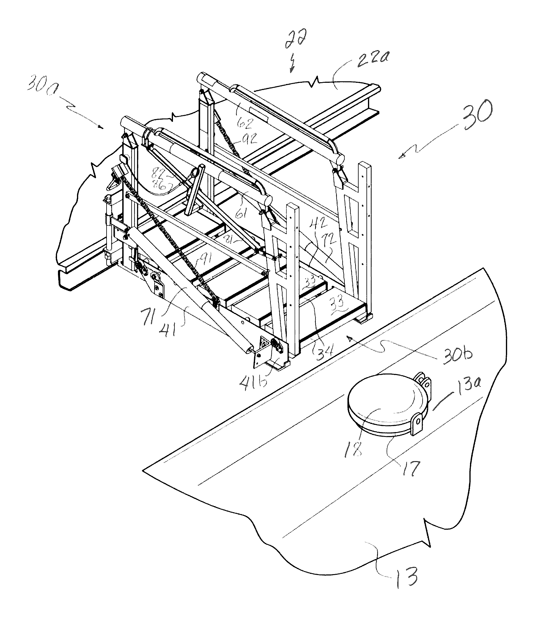
  • Device for resisting lifting of a gangway and gangway fitted with such device
  • Device for resisting lifting of a gangway and gangway fitted with such device
  • Device for resisting lifting of a gangway and gangway fitted with such device

Examples


Embodiment Construction

[0026]Reference will now be made in detail to present embodiments of the invention, one or more examples of which are illustrated in the accompanying drawings. The detailed description uses numerical and letter designations to refer to features in the drawings. Like or similar designations in the drawings and description have been used to refer to like or similar parts of embodiments of the invention.

[0027]Each example is provided by way of explanation of the invention, not limitation of the invention. In fact, it will be apparent to those skilled in the art that modifications and variations can be made in the present invention without departing from the scope or spirit thereof. For instance, features illustrated or described as part of one embodiment may be used on another embodiment to yield a still further embodiment. Thus, it is intended that the present invention covers such modifications and variations as come within the scope of the appended claims and their equivalents.

[0028...


PUM


Abstract

A sprung gangway that is counterbalanced to remain in a given degree of extension or retraction includes a lifting resistance device that includes a linear index rail that slides selectively into and out of a hollow sheath unless engaged by a locking paw that is pivotally mounted to the sheath via a pivot bar, which when pivoted by tugging on a release cord effects disengagement of the locking paw and thereby permits raising of the gangway from the lowered working orientation to a storage orientation.

Description

CROSS-REFERENCE TO RELATED APPLICATIONS[0001]The present application claims priority benefit to and is a continuation-in-part application to patent application Ser. No. 14 / 738,040, filed on Jun. 12, 2015, which is hereby incorporated herein in its entirety by this reference for all purposes.STATEMENT REGARDING FEDERALLY SPONSORED RESEARCH OR DEVELOPMENT[0002]Not applicable.FIELD OF THE INVENTION[0003]The subject matter disclosed herein generally involves fall protection equipment for accessing the tops of rolling stock, and particularly a so-called sprung gangway that can be deployed from one end of an elevated loading platform down onto the tops of rolling stock.BACKGROUND OF THE INVENTION[0004]In accessing the tops of rolling stock (tank trucks, tank railroad cars, etc.), a gangway or bridge is used to allow workers to move from an elevated loading platform to the top of the rolling stock. Such a gangway often includes self-leveling steps and is pivotally mounted to a platform tha...

Claims


Application Information

Patent Timeline
Patent Type & Authority Patents(United States)
IPC IPC(8): E01D15/00E01D19/04E01D15/02
CPCE01D15/02E01D19/04B60R3/005
Inventor WILLARD, RONALD D.ELVINGTON, MATTHEW S.
Owner SAM CARBIS ASSET MANAGEMENT
Learn More