Eureka AIR delivers breakthrough ideas for toughest innovation challenges, trusted by R&D personnel around the world.

Methods, systems, and devices for surgical visualization and device manipulation

a surgical visualization and device technology, applied in the field of surgical visualization and device manipulation, can solve the problems of limited maneuverability of tools, limited surgeon's dexterity and vision, and additional incisions may be required

Active Publication Date: 2017-02-28
BOARD OF RGT UNIV OF NEBRASKA
View PDF535 Cites 605 Cited by
  • Summary
  • Abstract
  • Description
  • Claims
  • Application Information

AI Technical Summary

Problems solved by technology

However, conventional techniques and tools for performing laparoscopic procedures can limit the dexterity and vision of the surgeon.
Given the size of the incisions, the maneuverability of the tools is limited and additional incisions may be required if an auxiliary view of the surgical site is needed.
The visual acuity of the surgeon may also be limited by the two-dimensional video display.
These constraints in both dexterous ability and vision limit the application of laparoscopic techniques to less complicated procedures.
However, these modified endoscopic tools present constraints similar to laparoscopic tools, including a diminished visual field and the use of a two-dimensional visual display.
Also, because the endoscopic tools must be flexible along their length in order to access the body cavity through a natural orifice, they present the additional challenges of determining and maintaining spatial orientation.
In addition, tissue manipulations are limited due to the necessity of applying force along the axis of the endoscope.

Method used


Image

  • Methods, systems, and devices for surgical visualization and device manipulation
  • Methods, systems, and devices for surgical visualization and device manipulation
  • Methods, systems, and devices for surgical visualization and device manipulation

Examples


example 1

[0117]The following is an exemplary kinematic design of the motion of one embodiment of a NOTES robotic device that can be used with any console as disclosed herein. The design is merely exemplary of one particular embodiment of a robotic device and is not intended to be limiting in any fashion, as any number of robotic devices can be used in conjunction with a console, as discussed above.

[0118]This particular design begins with a kinematic model of the robotic device, as shown in FIG. 15A. Here the kinematic model of the NOTES robot is shown overlaid on the robot schematic in FIG. 15A. The robot is a 2-DOF planar manipulator with a rotational shoulder joint A and prismatic arm B denoted by joint variables θ2 and a2 respectively.

[0119]The Denavit-Hartenberg parameters for the robot are shown in Table 1. The parameter α0 defines the angle of rotation of the robot with respect to a universal frame {0} that is used to introduce gravity. Parameters a1 and a3 are constants defining the b...

example 2

[0130]The following is an exemplary design of the motion of one embodiment of the shoulder joint of a NOTES robotic device. Here, a departure from typical joint designs was required because of a desire to keep the arm in plane with the body of the robotic device. One example of a kinematic model of the shoulder joint of the NOTES robotic device is shown in FIG. 16. In the present mechanism a powerscrew applies a force (Fs) to a slider constrained to move only in the y-direction. The slider mechanism is coupled to the robotic arm (ac) by a link (bd) with rotational degrees of freedom at each end. Length (ab) is constant and defines the length of the arm from the rotation point (a) to the linkage pin (b). Length (ad) represents the distance between the rotation point (a) and the slider (d) Angle θ1 is the angle between (ab) and (ad). For this particular example, link lengths of the model are shown in Equations 8-11.

[0131]ab_=lEquation⁢⁢8⁢ac_=a3⁢maxEquation⁢⁢9ad_=rEquation⁢⁢10bd_=dEqua...

example 3

[0136]The following is an exemplary design of the motion of one embodiment of the manipulators of the console. In this example, laparoscopic tool handles are used to control the movement of the NOTES robotic device. Natural and realistic control of the robotic device was achieved by requiring the laparoscopic tool to rotate about the same point as the robotic arm. This point is shown to be physically the same point; however, this point could be a virtual point. Relative motion with respect to the virtual point when the virtual point is not physically in the same location for both the console and the robotic device would create the same effect.

[0137]In the present example, an “offset planar hinge” similar to that shown in U.S. Pat. No. 5,657,584 was used. The linkage allows the manipulators to rotate about a remote point. An example of an offset planar hinge joint is shown in FIG. 17. The offset planar hinge joint shown in FIG. 17 is similar to offset planar hinge joint shown and des...


PUM


Abstract

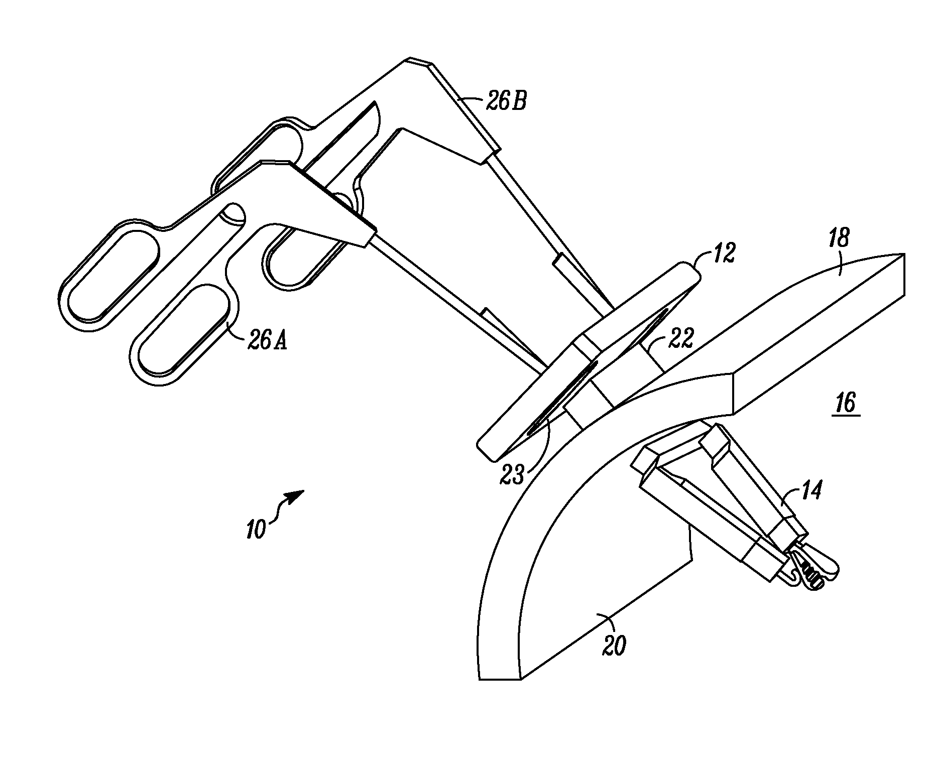
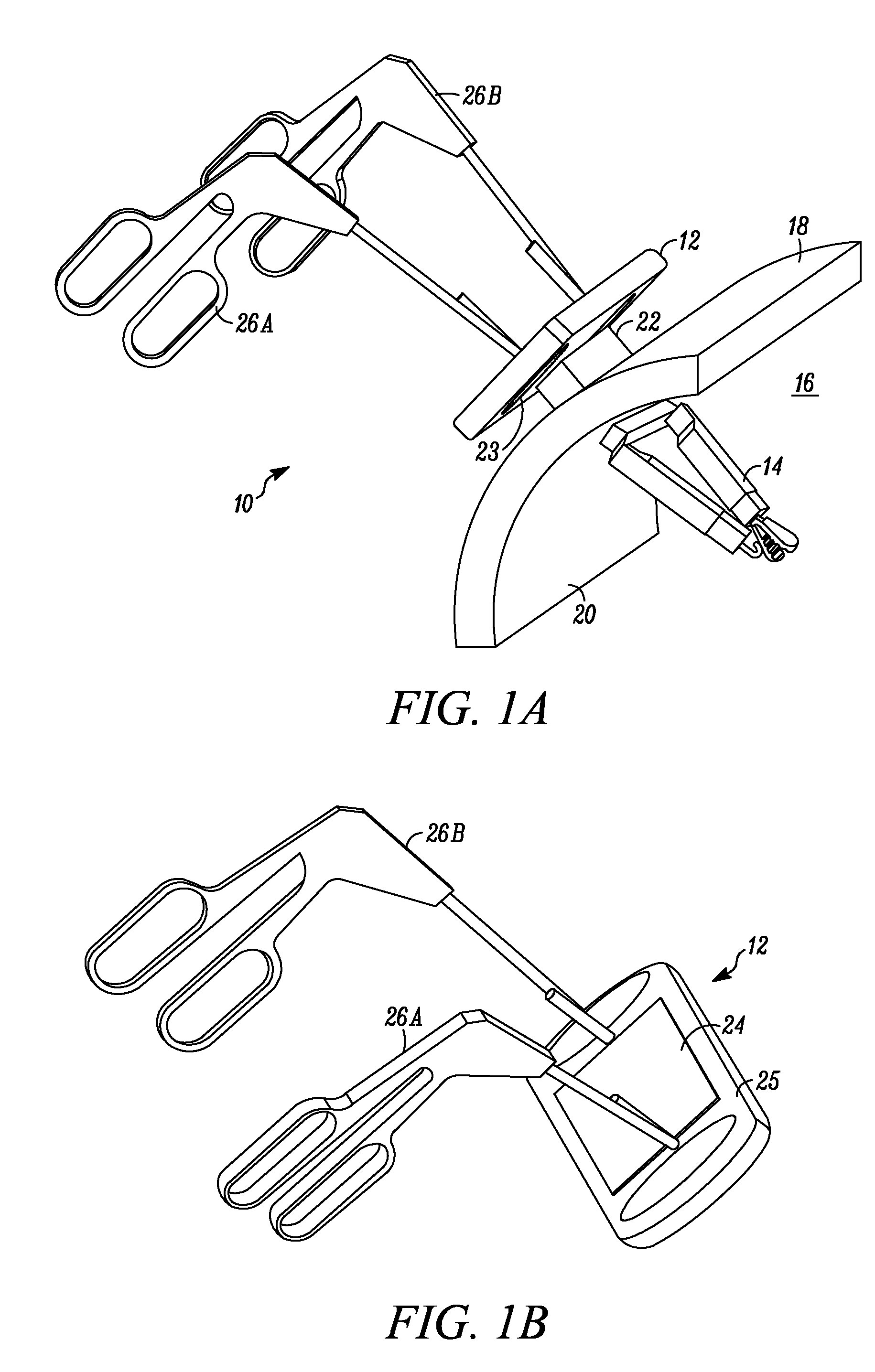
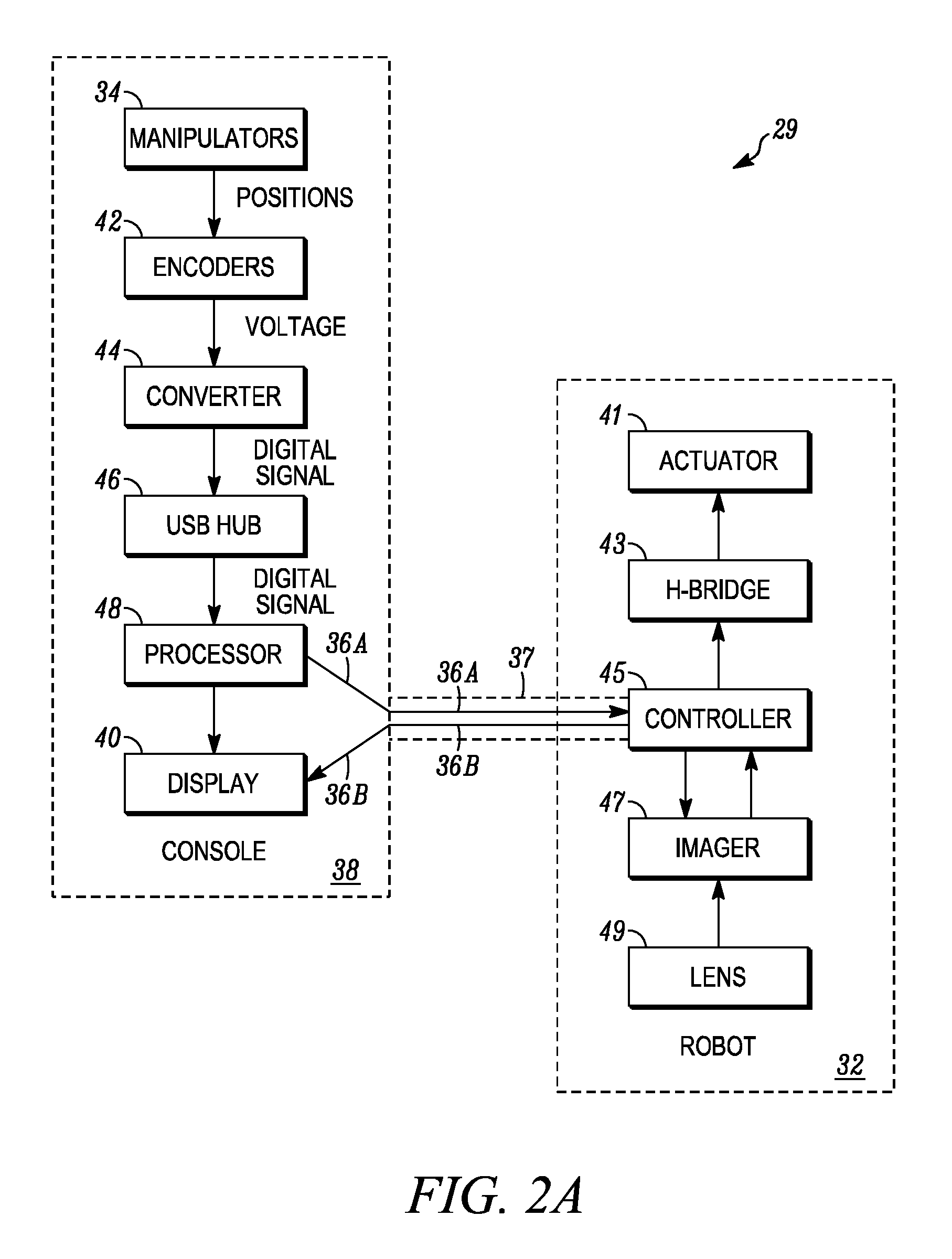
A surgical device includes a console having a visual display and a manipulator arm, a robotic device having a camera and a connection component. The robotic device is configured to be positioned completely within a body cavity. The camera is configured to transmit visual images to the visual display. The connection component operably couples the console and the robotic device. The manipulator arm is positioned relative to the visual display so as to appear to be penetrating the visual display.

Description

CROSS-REFERENCE TO RELATED APPLICATION(S)[0001]This application claims priority to U.S. Provisional Patent Application Ser. No. 60 / 890,691, filed Feb. 20, 2007 and titled “Methods, Systems, and Devices for Surgical Visualization and Device Manipulation;” U.S. Provisional Patent Application Ser. No. 60 / 956,032, filed Aug. 15, 2007 and titled “Methods, Systems, Devices of Robotic Medical Procedures;” and U.S. Provisional Patent Application Ser. No. 60 / 983,445, filed Oct. 29, 2007 and titled “Methods and Systems for Instructor and Student Operation of Surgical Devices,” all of which are hereby incorporated herein by reference in their entireties.FIELD OF THE INVENTION[0002]The present invention relates to a console for use in surgical procedures. More specifically, the console includes external manipulation components and a visual display that can be used in conjunction with an internal robotic device to minimize trauma to a patient during surgery.BACKGROUND OF THE INVENTION[0003]Open ...

Claims


Application Information

Patent Timeline
Patent Type & Authority Patents(United States)
IPC IPC(8): A61B1/00A61B17/00A61B1/04A61B1/06A61B17/29A61B1/313
CPCA61B17/00234A61B34/70A61B34/74A61B90/36A61B1/06A61B1/3132A61B17/29A61B34/30A61B90/37A61B2017/2919A61B2034/302A61B2034/742A61B2090/372A61B2090/373
Inventor FARRITOR, SHANE M.RENTSCHLER, MARKLEHMAN, AMYWOOD, NATHAN A.BOCK, ADAMPRIOR, REED
Owner BOARD OF RGT UNIV OF NEBRASKA
Why Eureka
Eureka Blog
Learn More