Musical sound control device, musical sound control method, program storage medium and electronic musical instrument

a technology of musical sound control and program storage medium, applied in the direction of instruments, electrotrophonic musical instruments, etc., can solve the problem of increasing manufacturing costs

Active Publication Date: 2017-02-28
CASIO COMPUTER CO LTD
View PDF14 Cites 14 Cited by
  • Summary
  • Abstract
  • Description
  • Claims
  • Application Information

AI Technical Summary

Benefits of technology

[0008]The present invention has been conceived in light of the above-described problem. An object of the present invention is to provide a musical sound control device by which touch control can be actualized without an increase in manufacturing cost, a musical sound control method, a program storage medium, and an electronic musical instrument.

Problems solved by technology

In this technology, there is a problem in that a pressure-sensitive sensor is required to be provided for each key on a keyboard and processing for uniformly adjusting the sensitivities of the respective pressure-sensitive sensors is required, which causes an increase in the manufacturing cost.

Method used


Image

  • Musical sound control device, musical sound control method, program storage medium and electronic musical instrument
  • Musical sound control device, musical sound control method, program storage medium and electronic musical instrument
  • Musical sound control device, musical sound control method, program storage medium and electronic musical instrument

Examples


first embodiment

A. Outer Appearance and Structure

[0036](1) Outer Appearance

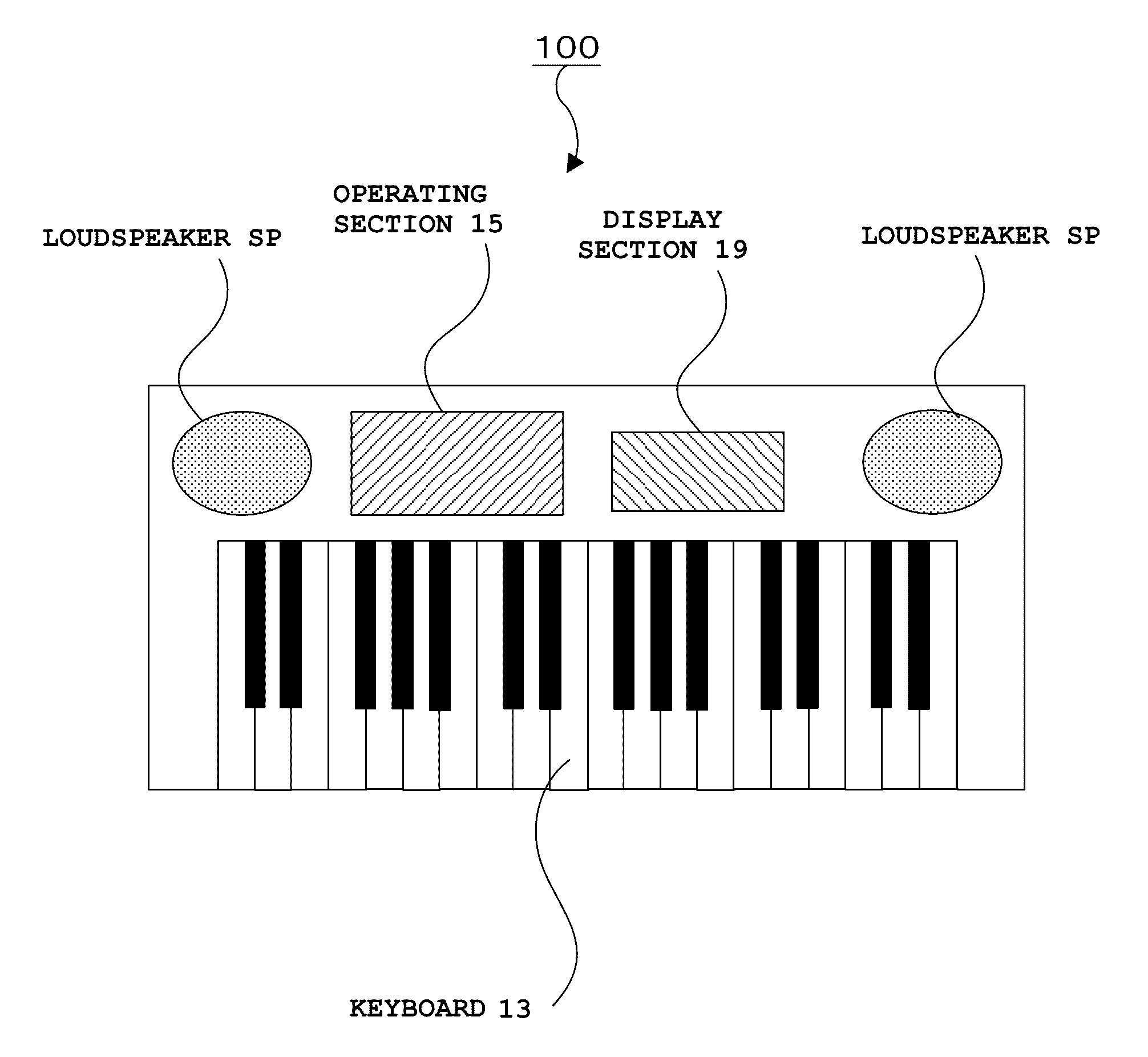
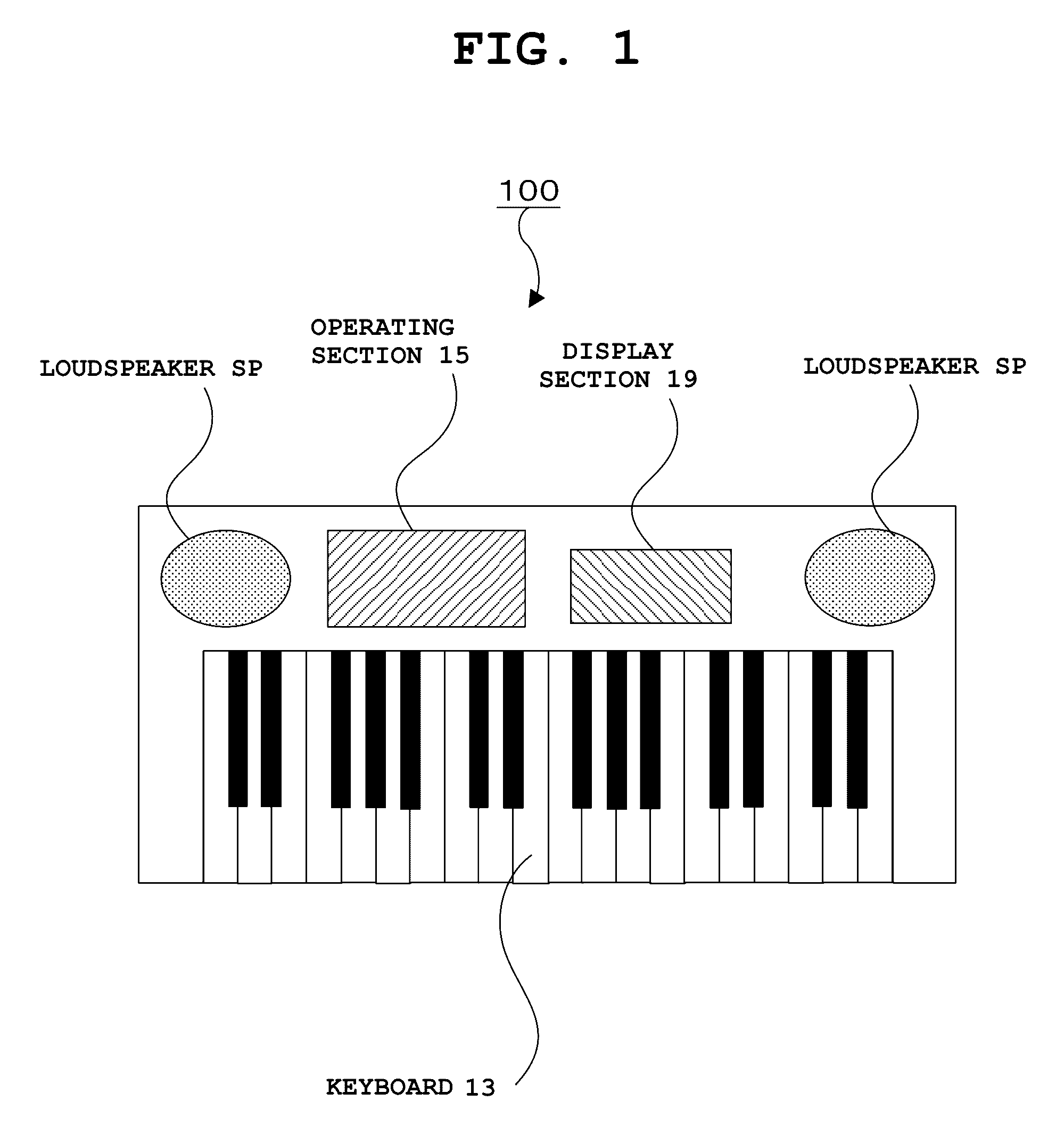
[0037]FIG. 1 is an external view of the outer appearance of an electronic musical instrument 100 including a musical sound control device according to a first embodiment of the present invention. The electronic musical instrument 100 depicted in the drawing has a rectangular-shaped housing, and includes a keyboard 13 arranged along the longitudinal direction on its front surface. On the left and right end sides of an operation panel provided in an area above this keyboard 13, a pair of loudspeakers SP is arranged. At the center, various operation switches constituting an operating section 15, and a display section 19 for displaying the setting status and the operation status of the musical instrument are arranged.

[0038](2) Structure

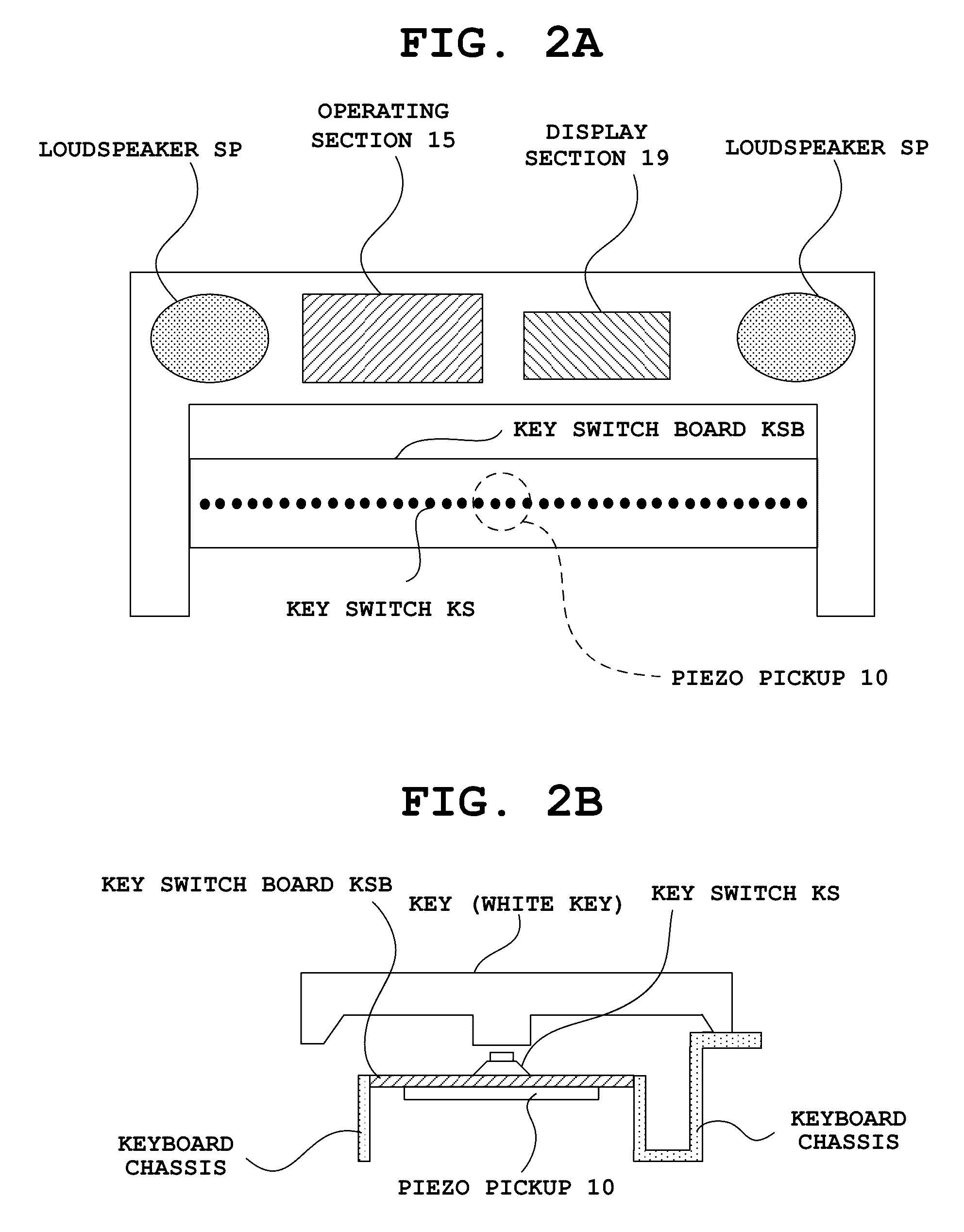
[0039]Next, a schematic structure of the keyboard 13 is described with reference to FIG. 2A and FIG. 2B. FIG. 2A and FIG. 2B are a planar view and a sectional view, respectively, for describing th...

modification example

D. Modification Example

[0085]Next, a modification example of the first embodiment is described with reference to FIG. 11. FIG. 11 is a planar and sectional view for describing the arrangement position of the piezo pickup 10 in the modification example. Note that components in FIG. 11 which are equivalent to those of the first embodiment in FIG. 2 are provided with the same reference numerals and descriptions therefor are omitted.

[0086]The modification example depicted in FIG. 11 is different from the first embodiment depicted in FIG. 2 in that the key switches KS arranged on the key switch board KSB are divided into those in a lower key area and those in an upper key area, and a lower-key-area piezo pickup 10-1 associated with each key switch KS on the lower key area side and an upper-key-area piezo pickup 10-2 associated with each key switch KS on the upper-key-area side are provided.

[0087]By the keyboard 13 being divided into the lower key area and the upper key area and the piezo...

second embodiment

A. Outer Appearance and Schematic Structure

[0089]FIG. 12 is a diagram showing the outer appearance and the schematic structure of an electronic percussion instrument 200 including a musical sound control device according to a second embodiment of the present invention. Note that components in FIG. 12 which are equivalent to those of the first embodiment in FIG. 1 are provided with the same reference numerals and descriptions therefor are omitted.

[0090]The electronic percussion instrument 200 depicted in FIG. 12, which has a housing having a substantially teardrop shape when viewed from top, includes a pad section 22 provided on its circular portion and the operating section 15 and the display section 19 provided on its tail portion. The pad section 22 is constituted by pad switches PS1 to PS4 and a dome-shaped pad P formed to cover these pad switches PS1 to PS4.

[0091]When portions of the pad P corresponding to the pad switches PS1 to PS4 are operated, the pad switches PS1 to PS4 ent...


PUM


Abstract

A piezo pickup which detects a key depression vibration occurred by a key depression operation is provided on the center of the lower surface of a key switch board where key switches of a keyboard are arranged. A CPU acquires the key number of a depressed key and a distance between the key switch of this key number and the piezo pickup in response to the key depression operation, and controls the sound volume and the tone color of a musical sound at a pitch corresponding to the key number based on control data acquired by correcting the detection output level (piezo input envelope waveform) of the piezo pickup in accordance with the acquired distance.

Description

CROSS-REFERENCE TO RELATED APPLICATION[0001]This application is based upon and claims the benefit of priority from the prior Japanese Patent Application No. 2014-19253.4, filed Sep. 22, 2014, the entire contents of which are incorporated herein by reference.BACKGROUND OF THE INVENTION[0002]1. Field of the Invention[0003]The present invention relates to a musical sound control device suitable for use in an electronic keyboard instrument including a keyboard and an electronic percussion instrument including a pad, a musical sound control method, a program storage medium, and an electronic musical instrument.[0004]2. Description of the Related Art[0005]Conventionally, a touch response method for controlling the sound volume of an emitted musical sound in accordance with a key touch or the like (the manner of depressing a key) has been known. Known examples of the touch response method include a method of controlling an initial touch by detecting a key depression speed when a key is dep...

Claims


Application Information

Patent Timeline
Patent Type & Authority Patents(United States)
IPC IPC(8): G10H1/32G10H3/00G10H1/34G10H1/055G10H3/14
CPCG10H1/344G10H1/0556G10H3/143G10H2220/221G10H2220/525
Inventor IWASE, HIROSHI
Owner CASIO COMPUTER CO LTD
Why Eureka
Try Eureka