
Suspension for mountain bicycles

a suspension system and mountain bike technology, applied in the field of mountain bike suspensions, can solve the problems of complex design, performance needs, and inability to overcome what appear to be fundamental design compromises

Active Publication Date: 2017-03-21
BERTHOLD BRIAN DAVID
View PDF15 Cites 9 Cited by
  • Summary
  • Abstract
  • Description
  • Claims
  • Application Information

AI Technical Summary

Benefits of technology

The system delivers a stiff response for climbing, enhanced stability and bump absorption for descending, and optimized travel for varying terrain, eliminating undesirable bobbing and improving traction and high-speed stability by automatically adjusting geometry and suspension characteristics in response to riding forces.

Problems solved by technology

While offering certain benefits, current mountain bike suspension systems suffer from a number of limitations, drawbacks and design compromises.
In contrast, downhill descents present very different, and apparently conflicting, performance needs.
Heretofore many efforts at improved mountain bike suspension have been attempted but have not overcome the what appear to be fundamental design compromises.
While these designs provide significant benefits as to performance and function of mountain bicycle suspension, they too are subject to a number of limitations that appear to require fundamental design compromises including needs for multiple shocks and biasing members among others.
There remains a long felt, unaddressed need for mountain bike suspension systems that provide fundamentally different performance and geometries across the gamut of potential riding conditions.

Method used


Image

  • Suspension for mountain bicycles
  • Suspension for mountain bicycles
  • Suspension for mountain bicycles

Examples


Embodiment Construction

[0019]Throughout the following description specific details are set forth in order to provide a more thorough understanding to persons skilled in the art. However, well known elements may not have been shown or described in detail to avoid unnecessarily obscuring the disclosure. Accordingly, the description and drawings are to be regarded in an illustrative, rather than a restrictive, sense.

[0020]The term “bicycle” used herein refers both to chain-driven pedal-powered bicycles and chain-driven motor-powered bicycles or motorcycles. While the exemplary embodiments disclosed herein have particular utility for mountain bicycles, they are also useful for any type of chain-driven bicycle or motorcycle.

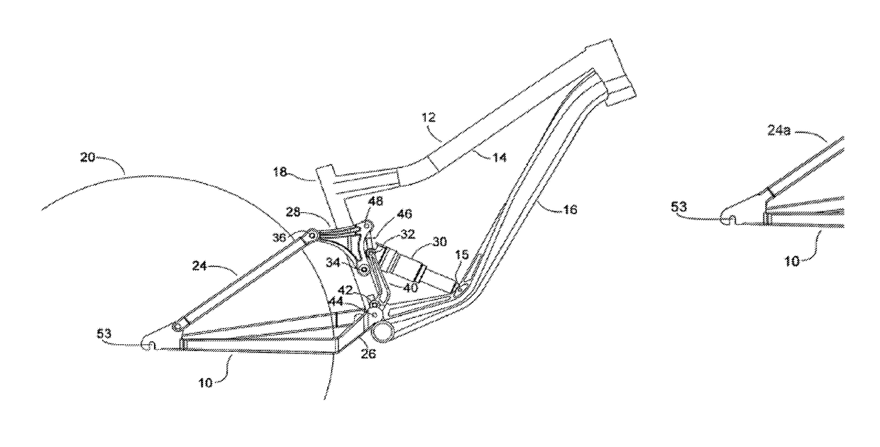
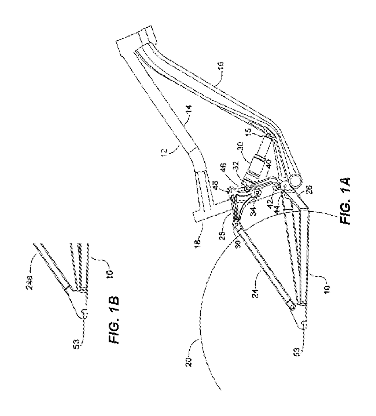
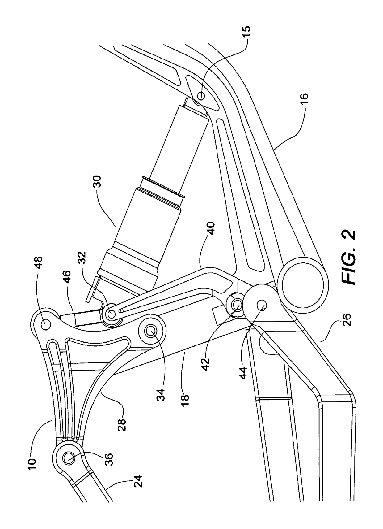
[0021]With reference to FIG. 1A, a rear wheel suspension system is designated as 10 mounted on bicycle frame 12 consisting of a top tube 14, down tube 16 and seat tube 18. Rear wheel 20 rotates on an axle (not shown) which is mounted at 53 on the chainstay 26 which is connected to a pair of...


PUM


Abstract

Unique suspension apparatuses, systems and methods useful for mountain bicycles among other applications are disclosed. In certain exemplary embodiments the suspension is self adjusting to meet different performance objectives. The suspension may utilize pedaling force to substantially stiffen or lock out movement of the suspension, for example, during climbing. The suspension may change its performance under reduced pedaling force to provide performance characteristics desired when a rider is descending. Certain exemplary embodiments include a rocker arm connected to a first frame portion at a first rocker arm pivot, connected to a seatstay at a second rocker arm pivot, and connected to a second link at a third rocker arm pivot. The first link is connected to the first frame portion at a first link pivot, connected to the chainstay at a second link pivot, and connected to the shock and the second link at a third link pivot.

Description

CROSS-REFERENCE TO RELATED APPLICATIONS[0001]This application is the National Phase of International Application PCT / US2013 / 024865, filed Feb. 6, 2013 which designated the U.S. and that International Application was published in English under PCT Article 21(2) on Aug. 15, 2013 as International Publication Number WO 2013 / 119616 A1. PCT / US2013 / 024865 claims priority to U.S. Provisional Application No. 61 / 595,272, filed Feb. 6, 2012. Thus, the subject nonprovisional application claims priority to U.S. Provisional Application No. 61 / 595,272, filed Feb. 6, 2012. The disclosures of both applications are incorporated herein by reference.BACKGROUND[0002]The present disclosure relates generally to the field of bicycle suspensions and geometry and more particularly mountain bicycle suspensions. Mountain bike suspension has offered a number of advantages to riders including the ability to ride extreme mountain and desert terrain as well as increasing comfort for the more casual rider. While of...

Claims


Application Information

Patent Timeline
Patent Type & Authority Patents(United States)
IPC IPC(8): B62K25/26B62K25/28B62K3/02B62K25/04
CPCB62K25/286B62K3/02B60G2204/421B60G2204/424B60G2300/12B62K2025/048
Inventor BERTHOLD, BRIAN DAVID
Owner BERTHOLD BRIAN DAVID
Learn More