Full spectrum light emitting arrangement

a light emitting arrangement and full spectrum technology, applied in semiconductor devices for light sources, lighting and heating apparatus, planar light sources, etc., can solve the problems of incandescent claimed full spectrum lamps, incandescent claimed full-spectrum lamps are also relatively energy-consuming, and no full spectrum lighting

Active Publication Date: 2017-03-21
LUMILEDS
View PDF14 Cites 7 Cited by
  • Summary
  • Abstract
  • Description
  • Claims
  • Application Information

AI Technical Summary

Benefits of technology

[0009]It is an object of the present invention to overcome this problem, and to provide a light emitting arrangement which produces a continuous spectrum light output.
[0013]The light emitting arrangement produces a more continuous spectrum, with smaller of virtually no dips. By arranging materials having different wavelength conversion properties in different domains, preferably in a plane, re-absorption of secondary emission can be avoided.
[0022]The light emitting arrangement may further comprise a shielding member arranged in the path of light from the solid state light source to the wavelength converting member. The shielding member is capable of preventing light emitted by the light source from reaching at least one wavelength converting domain. Hence, by preventing emission of at least one sub-range, the emission spectrum may be tuned by elimination of certain wavelengths.

Problems solved by technology

However, the spectra of these incandescent lamps are still showing spikes and / or dips.
In addition, incandescent claimed full-spectrum lamps are also relatively energy-consuming.
Using direct LEDs no full spectrum lighting can be made.
Another drawback of using different direct LEDs is that each LED needs a different driving current.
Using phosphor-converted light emitting diodes (LEDs) it is also difficult to obtain full spectrum lighting without spikes and / or dips in the spectrum.
It is difficult to fill in the gaps of this spectrum using conventional organic and inorganic phosphors, which are broad band emitters, to obtain continuous full back body emission.
However, a drawback of the device described in this document is that re-absorption of the secondary light may lead to reduced efficiency and it becomes difficult to make a fine tuning of a desired spectrum.

Method used


Image

  • Full spectrum light emitting arrangement
  • Full spectrum light emitting arrangement
  • Full spectrum light emitting arrangement

Examples


Embodiment Construction

[0044]The present invention will now be described more fully hereinafter with reference to the accompanying drawings, in which currently preferred embodiments of the invention are shown. This invention may, however, be embodied in many different forms and should not be construed as limited to the embodiments set forth herein; rather, these embodiments are provided for thoroughness and completeness, and fully convey the scope of the invention to the skilled person.

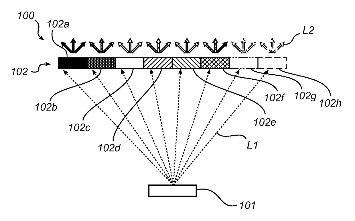
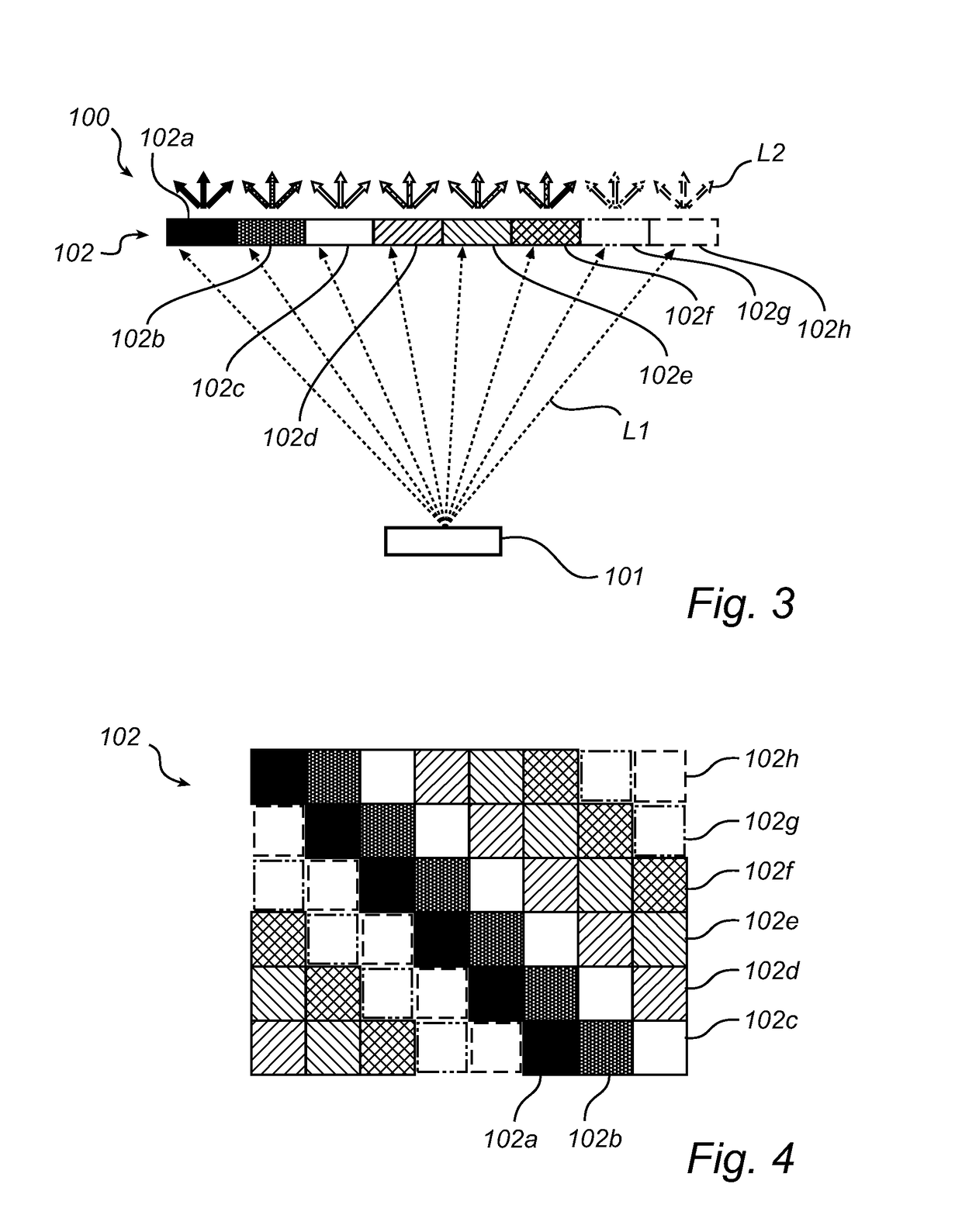
[0045]The present inventors have found that a light emitting arrangement using a solid state light source, e.g. a UV, violet or blue LED, and a plurality of quantum dots, a continuous, full black body emission spectrum can be obtained.

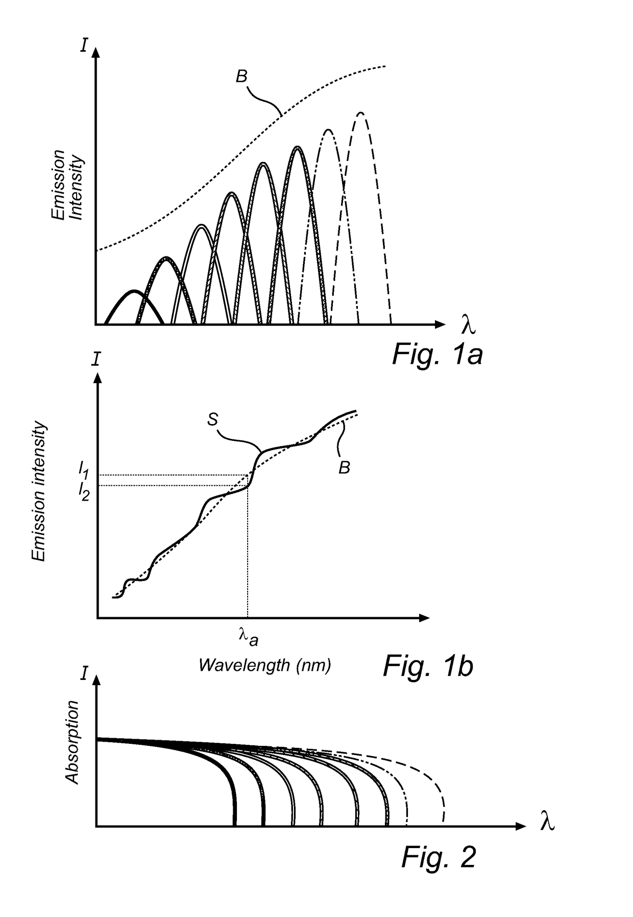
[0046]FIG. 1a schematically illustrates a spectrum that can be obtained by a light emitting arrangement according to embodiments of the invention. The graph shows intensity as a function of wavelength (λ). The first peak (to the left) represents the shortest visible wavelength, violet light, w...


PUM


Abstract

A light emitting arrangement is provided, comprising:—a solid state light source (101) adapted to emit primary light (L1); and—a wavelength converting member (102) comprising a plurality of wavelength converting domains (102a, 102b, 102c, etc) for converting primary light into secondary light (L2), each wavelength converting domain thereby providing a sub-range of the total light output spectrum, wherein at least some of said wavelength converting domains are arranged as an array and comprise quantum dots, wherein different wavelength converting domains comprise quantum dots having different secondary light emission ranges providing different sub-ranges of the total light output spectrum, and wherein a sub-range provided by each wavelength converting domain overlaps or is contiguous with at least one other sub-range provided by another wavelength converting domain. By arranging materials having different wavelength conversion properties in different domains, preferably in a plane, re-absorption of secondary emission can be avoided.

Description

CROSS-REFERENCE TO PRIOR APPLICATIONS[0001]This application is the U.S. National Phase application under 35 U.S.C. §371 of International Application No. PCT / IB2013 / 052652, filed on Apr. 3, 2013, which claims the benefit of U.S. Provisional Patent Application No. 61 / 620,522, filed on Apr. 5, 2012. These applications are hereby incorporated by reference herein.FIELD OF THE INVENTION[0002]The present invention relates to solid state light emitting arrangements comprising using quantum dots as wavelength conversion materials.BACKGROUND OF THE INVENTION[0003]In the development of new products within the field of lighting much effort is made to design light sources producing a full spectrum, i.e. a light output including all wavelengths of visible light. There is also a demand for light sources with a continuous spectrum showing black body emission at various correlated color temperatures (CCTs). Such full spectrum lighting is white light having a smooth intensity spectrum without sharp s...

Claims


Application Information

Patent Timeline
Patent Type & Authority Patents(United States)
IPC IPC(8): F21K99/00H01L33/50F21V9/10F21V9/16F21V14/00F21V9/40F21Y101/00F21Y105/00
CPCF21K9/64F21V9/10F21V9/16F21V14/003H01L33/504H01L33/508F21Y2101/00F21Y2105/00F21Y2115/15F21Y2115/30F21V9/30F21V9/40F21Y2115/10F21V9/45F21V9/32H01L33/50
Inventor HIKMET, RIFAT ATA MUSTAFAVAN BOMMEL, TIES
Owner LUMILEDS
Why Eureka
Try Eureka