
Non-integral segmented angel-wing seal

a non-integral, segmented technology, applied in the direction of blade accessories, leakage prevention, machines/engines, etc., can solve the problem that the portion of the hank adjacent to the bucket or the blade root portion does not provide sufficient space for the conventional hank portion seal

Active Publication Date: 2017-03-28
GE INFRASTRUCTURE TECH INT LLC
View PDF10 Cites 11 Cited by
  • Summary
  • Abstract
  • Description
  • Claims
  • Application Information

AI Technical Summary

Benefits of technology

This solution enables effective sealing in turbomachines by providing a flexible and adaptable angel-wing seal arrangement that can be tailored to various bucket and blade designs, enhancing sealing performance and accommodating different materials for temperature compatibility.

Problems solved by technology

There are occasions, however, when it is desired to utilize bucket or blade designs that are unable to accommodate the usual angel-wing seal configurations.
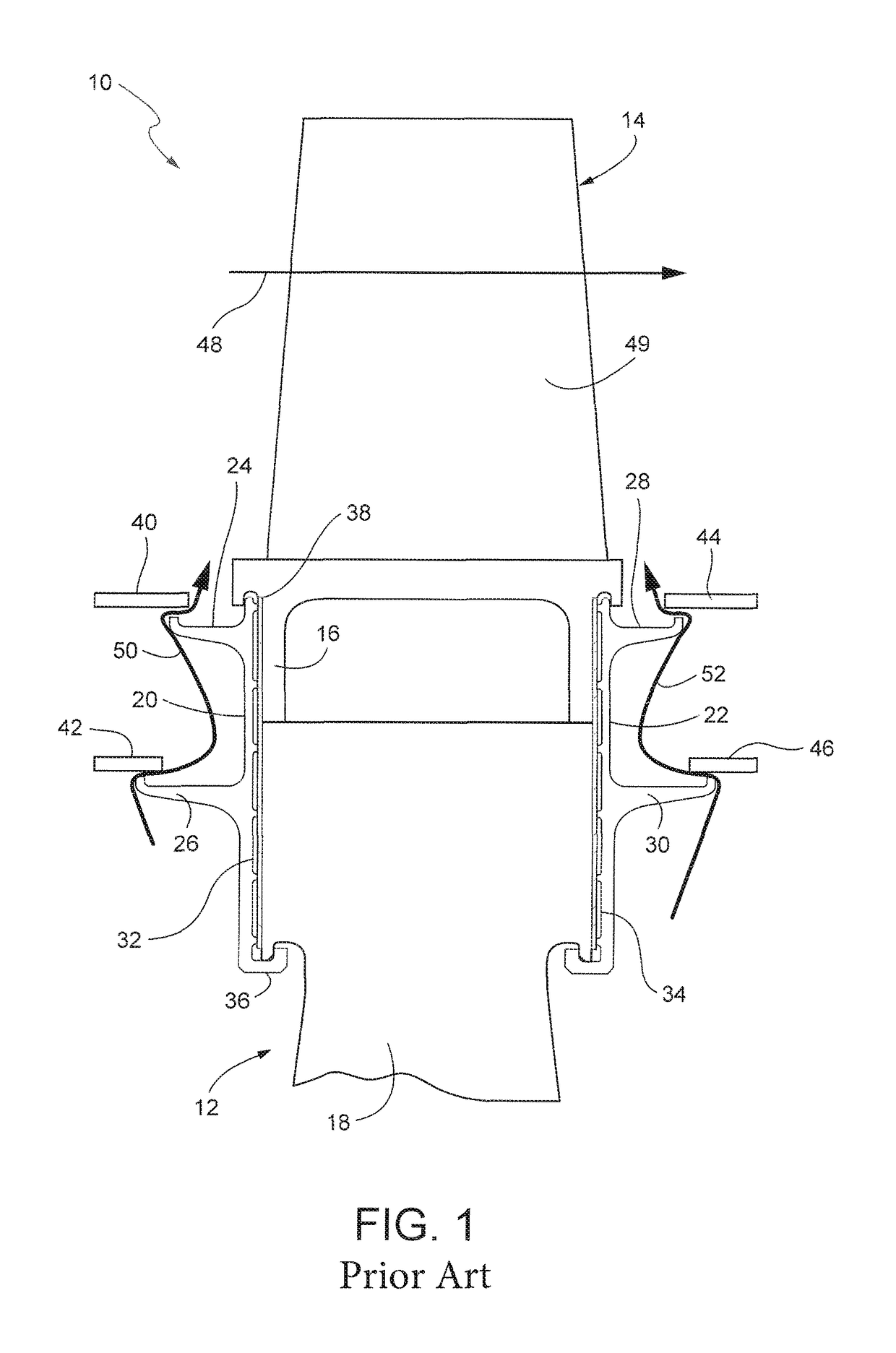
For example, in a short-shank bucket or blade design, the shorter shank portions adjacent the bucket or blade root portions do not provide sufficient room for conventional angel-wing seals which, in many applications, are provided in a double-stacked arrangement with radially-spaced inner and outer seal elements.

Method used


Image

  • Non-integral segmented angel-wing seal
  • Non-integral segmented angel-wing seal
  • Non-integral segmented angel-wing seal

Examples


Embodiment Construction

[0014]FIG. 1 shows a cross-sectional view of a relevant portion of a turbomachine 10 which includes a rotor or shaft (not shown) mounting a plurality of wheels 12 (one shown). Each wheel supports an annular array of buckets 14 (one shown), and each wheel is flanked by stationary vanes (not shown) or other static or rotating hardware. The manner in which stationary vanes of the upstream nozzle feed combustion gases or steam to the rotating buckets to drive the wheels and rotor is well known and need not be described here in any further detail.

[0015]It will be appreciated that the term “bucket” usually refers to the airfoil-shaped vanes (and associated mounting portion) employed in the turbine section(s) of turbomachines, while the term “blade” usually refers to the airfoil-shaped vanes (and associated mounting portions) typically employed in the compressor section of the machines. While the description below refers to “buckets”, it is to be understood that the seal configurations are...


PUM


Abstract

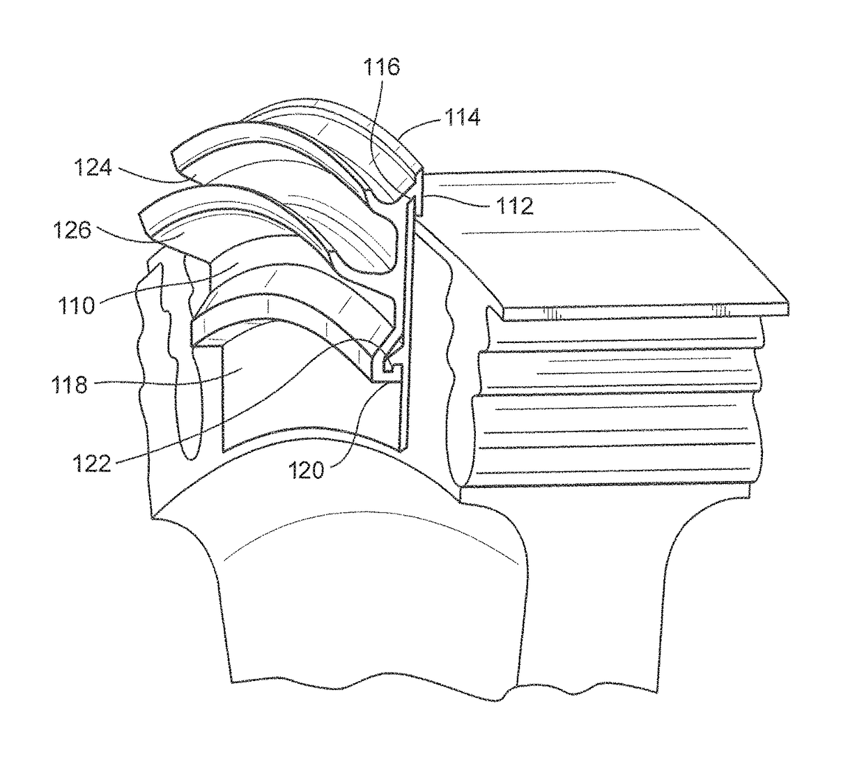
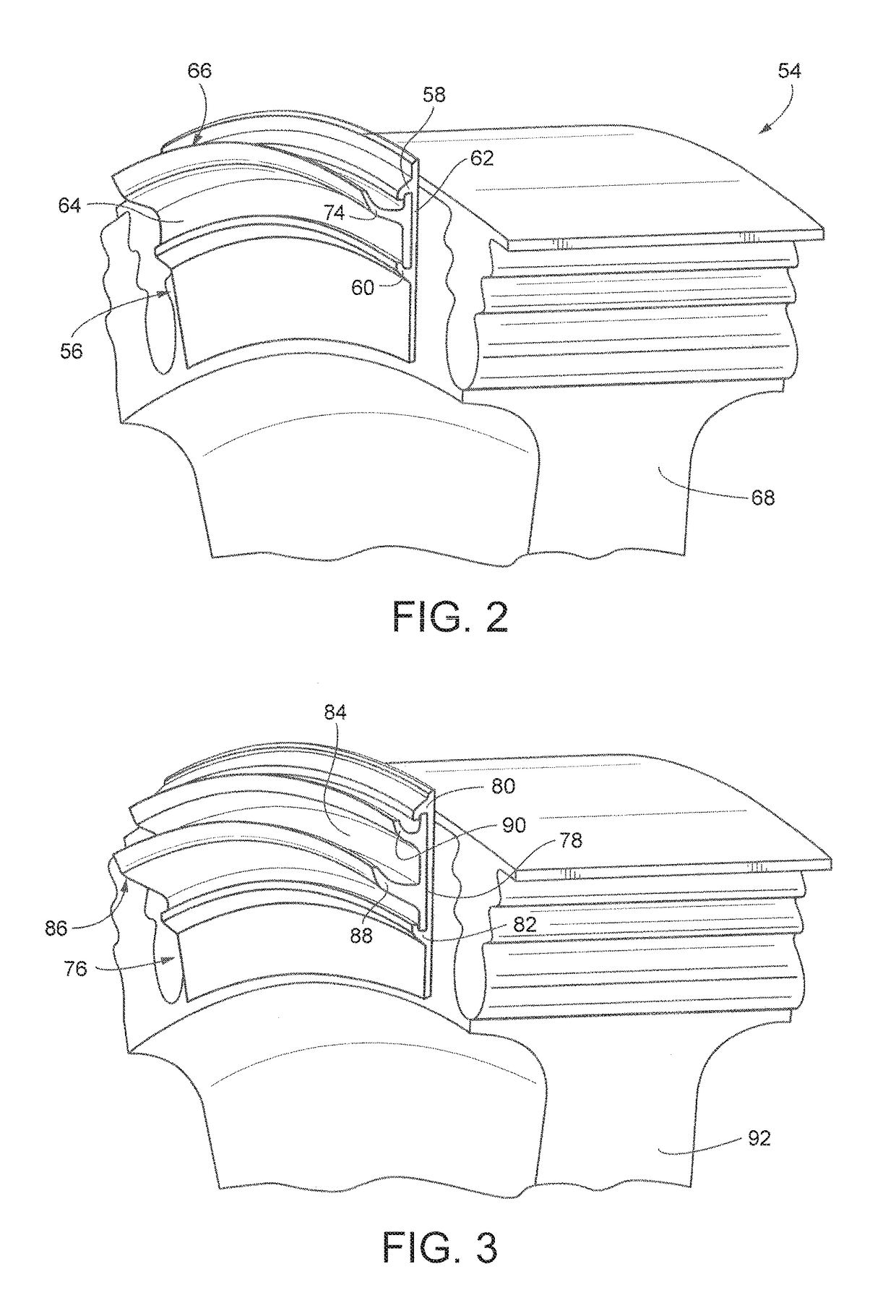
A cover plate adapted to axially overlie root or shank portions of one or more buckets or blades secured to a turbomachine wheel, includes an arcuate cover plate body adapted to be secured to the turbomachine wheel so as to cover a root portion of at least one of the turbine buckets or blades; and at least one arcuate angel-wing seal segment detachably secured to one side of the arcuate cover plate body.

Description

[0001]The present invention relates generally to seals related to the flow of combustion gases in turbomachines, and specifically, to cover plates supporting seals (for example, so-called “angel-wing” seals) that over-lie the root portions of blades or buckets in the compressor and / or turbine sections of such machines.BACKGROUND OF THE INVENTION[0002]Cover plates are generally used on turbomachine wheels, along the upstream and downstream faces of buckets or blades mounted on the wheels. The cover plates often support axially-projecting seals, generally referred to as angel-wings seals, that interact with seal lands on adjacent stationary and / or rotating hardware. These seals are intended to prevent both the ingress of hot gases into the rotor wheelspace radially inward of the buckets or blades, and the egress of the cooler wheelspace air into the hot gas path. The angel-wing seals may be integrally cast with the bucket or blade, or may comprise non-integral, separate plates mechani...

Claims


Application Information

Patent Timeline
Patent Type & Authority Patents(United States)
IPC IPC(8): F01D11/00F01D5/30
CPCF01D11/006F01D5/3015F01D11/001
Inventor WONDRASEK, MICHAEL ANTHONYHOGBERG, NICHOLAS ALVIN
Owner GE INFRASTRUCTURE TECH INT LLC
Learn More