Lens and method for correcting vision of a user

a technology for users and lenses, applied in the field of lenses, can solve the problems of slowing down myopia aggravation of users, and not being suitable for various eyeball configurations of different users, and achieve the effect of arresting the progression of myopia or hyperopia

Active Publication Date: 2017-04-04
BRIGHTEN OPTIX CORP
View PDF12 Cites 0 Cited by
  • Summary
  • Abstract
  • Description
  • Claims
  • Application Information

AI Technical Summary

Benefits of technology

[0007]Therefore, the object of the present invention is to provide a lens capable of forming various images spaced apart from the retina of the user to arrest progression of myopia or hyperopia.

Problems solved by technology

It has been proven in many researches and studies that such design may slow down myopia aggravation of the user.
However, the outer zone 12 of the conventional lens 1 having a single curvature can only provide a defocus image in front of the retina 19 at a fixed position, which may not be suitable for various eyeball configurations of different users.

Method used


Image

  • Lens and method for correcting vision of a user
  • Lens and method for correcting vision of a user
  • Lens and method for correcting vision of a user

Examples


Embodiment Construction

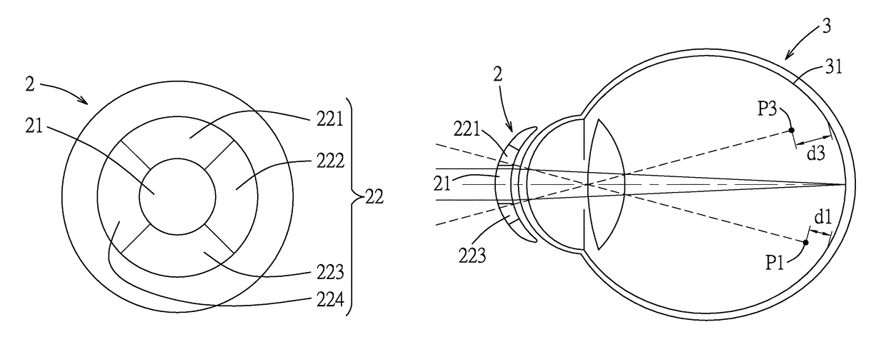
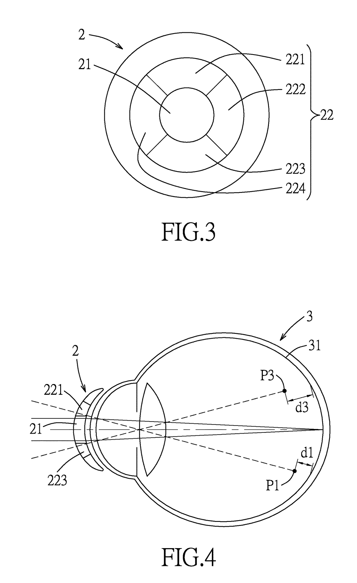
[0020]Referring to FIGS. 3 and 4, the first preferred embodiment of the lens 2 for correcting vision of a user according to the present invention includes a central zone 21 and an outer zone 22. The central zone 21 is configured to cause light passing therethrough to form an image on a retina 31 of an eye of the user. Note that the lens 2 may be configured for use in a pair of glasses, or may be configured as a contact lens.

[0021]The outer zone 22 surrounds the central zone 21, and has a plurality of different aspherical coefficients for respectively causing light passing therethrough to form images spaced apart from the retina 31. In this embodiment, the outer zone 22 includes a plurality of arc segments 221, 222, 223, 224 angularly connected to one another to surround the central zone 21. Connected two of the arc segments 221, 222, 223, 224 have respective different aspherical coefficients so as to cause light passing therethrough to form respective defocus images at different dis...


PUM


Abstract

A lens for correcting vision of a user includes a central zone and an outer zone. The central zone is configured to cause light passing therethrough to form an image on a retina of an eye of the user. The outer zone surrounds the central zone and has a plurality of different aspherical coefficients for respectively causing light passing therethrough to form images spaced apart from the retina.

Description

CROSS-REFERENCE TO RELATED APPLICATION[0001]This application claims priority to Taiwanese Application No. 102118442, filed on May 24, 2013.BACKGROUND OF THE INVENTION[0002]1. Field of the Invention[0003]This invention relates to a lens, more particularly to a lens for correcting vision of a user.[0004]2. Description of the Related Art[0005]Referring to FIGS. 1 and 2, a conventional lens 1 for correcting vision of a user includes a central zone 11, and an outer zone 12 surrounding the central zone 11. The central zone 11 and the outer zone 12 have different curvatures. Ina case of the user being myopic, the central zone 11 causes light passing therethrough to forma clear image on a retina 19 of an eye of the user, and the outer zone 12 causes light passing therethrough to form an image in front of the retina 19 at a point (Q), i.e., a blur or defocus image, which is slightly myopic to the user. It has been proven in many researches and studies that such design may slow down myopia ag...

Claims


Application Information

Patent Timeline
Patent Type & Authority Patents(United States)
IPC IPC(8): G02C7/04G02C7/06
CPCG02C7/044G02C7/045G02C2202/24
Inventor WU, RICHARD
Owner BRIGHTEN OPTIX CORP
Why Eureka
Try Eureka