Quick mixing baby formula cylinder and system
a technology of formula cylinder and baby, which is applied in the field of baby formula bottles, can solve the problems of inconvenience for parents or caregivers, and potentially messy situations
- Summary
- Abstract
- Description
- Claims
- Application Information
AI Technical Summary
Problems solved by technology
Method used
Image

Examples
second embodiment
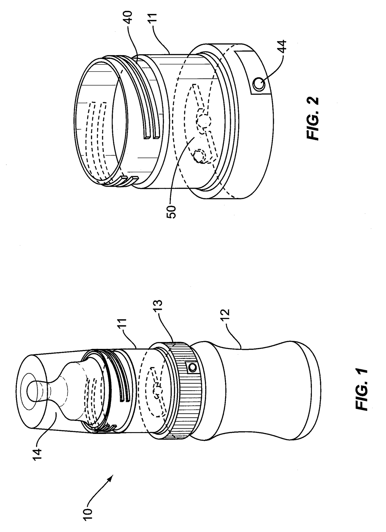
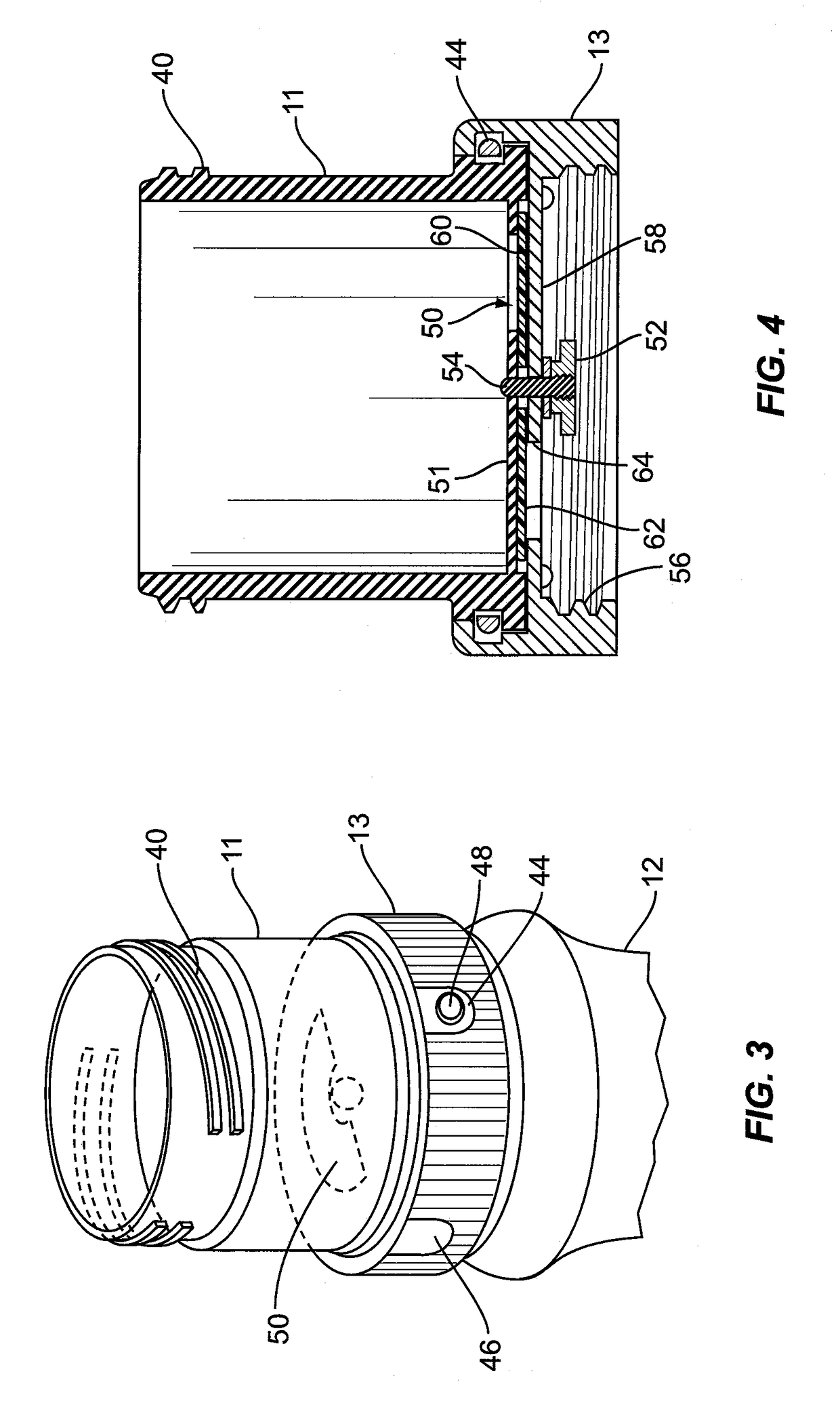
[0028]FIG. 5 is a vertical sectional view of a second embodiment cutting through the release button 18 longitudinally, and showing both the upper cylinder 11 with its nipple mating threads 22, and the lower attachment ring 13. Above the bottle mating threads 24, the lower ring 13 has a built-in horizontal member that covers about half of the cross section area defined by the inside diameter of ring 13. Also built into the upper inside surface of attachment ring 13 are a circumferential ledge 23, a circumferential groove 25, and a cavity 34. Release button 18 has an attached leg 32 that engages with cavity 34. Also attached to button 18 is a spring 26 that fits into the cavity 28 molded into recessed area 30 of the upper cylinder 11. The cylinder 11 has a floor 21 across slightly more than half of the bottom area.
[0029]FIG. 6 is a perspective view from above with the two apertures aligned to create an opening 16. When the user desires to blend the formula powder stored in cylinder 11...
third embodiment
[0030]the invention is shown in FIG. 7 via a vertical sectional view of the device. The upper cylindrical chamber 70 having external threads adjacent the top end, for mating to a standard baby bottle nipple, is fused at three-quarters of its bottom periphery, to lower ring 72, which has internal threads 76 to mate to a standard baby bottle. Where the other one-quarter of the bottom edge of cylindrical chamber 70 abuts the top edge of ring 72. Rubber-like partial 0-rings 78 are imbedded in the edge such that the two partial 0-rings 78 are tightly compressed against one another. The cylindrical chamber 70, has a bottom floor 80 with a sizeable off-center aperture 82 and a central fused-in pin 84.
[0031]Suspended just below the bottom floor 80 is a rotatable horizontal disc 86 with a central orifice slightly larger than the outer diameter of central pin 84. Adhered to the top surface of disc 86 is a rubber-like seal pad 94 covering an area slightly larger than that of aperture 82. Horiz...
fourth embodiment
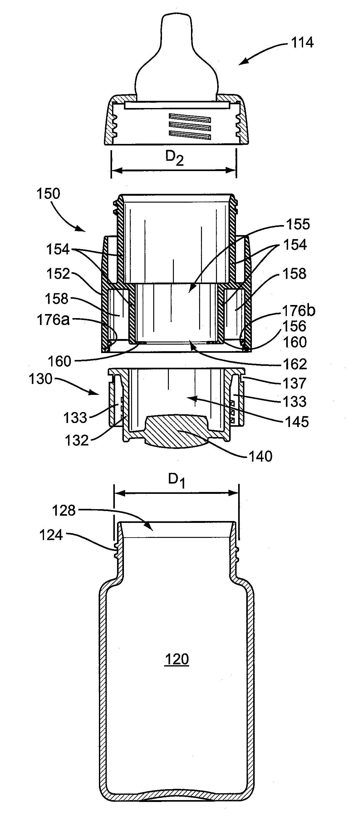
[0034]the invention is shown in FIGS. 8 through 14. The bottle system 110 shown in FIGS. 8, 9, 10A and 10B may include a nipple assembly 114, chamber assembly 150, plug assembly 130, plug 140 and a bottle 120. The chamber assembly 150 and the plug assembly 130 cooperate to form the seal 180 in the bottle system 110. As shown in FIG. 9, the seal 180 includes a partition 160 and plug 140 in contact and that separate the first and second compartments 182 and 184. The compartments may separately hold water and / or powdered formula.
[0035]As shown in FIG. 10A, the plug assembly 130 may have a groove 137 for receiving an o-ring, gasket, or other type of sealant. The groove 137 and o-ring (not shown) may minimize water, or mixed formula, from leaking out of the bottle system 110 during feeding or mixing. In addition, the groove 137 and o-ring may limit movement of the chamber assembly 150 when using the bottle system 110, as will be discussed below.
[0036]Referring to FIG. 9, a user may add t...
PUM
 Abstract
Description
Claims
Application Information
 - R&D Engineer
- R&D Manager
- IP Professional
- Industry Leading Data Capabilities
- Powerful AI technology
- Patent DNA Extraction
Browse by: Latest US Patents, China's latest patents, Technical Efficacy Thesaurus, Application Domain, Technology Topic.
© 2024 PatSnap. All rights reserved.Legal|Privacy policy|Modern Slavery Act Transparency Statement|Sitemap