Signal line module and communication terminal apparatus

a technology of communication terminals and signal lines, which is applied in the direction of waveguides, resonant antennas, waveguide type devices, etc., can solve the problems of power transmission loss caused by impedance mismatches between lines and connectors, and achieve low-loss power transmission, reduce or prevent significant degradation of radiation characteristics of antennas, and reduce size

Active Publication Date: 2017-05-23
MURATA MFG CO LTD
View PDF11 Cites 0 Cited by
  • Summary
  • Abstract
  • Description
  • Claims
  • Application Information

AI Technical Summary

Benefits of technology

[0007]Accordingly, preferred embodiments of the present invention provide a signal line module in which power transmission loss and degradation of the antenna characteristics of a radiation element are significantly reduced or prevented, and provide a communication terminal apparatus including such a signal line module.
[0020]According to various preferred embodiments of the present invention, the high-frequency line portion and the matching circuit portion preferably are integrated. Hence, generation of standing waves corresponding to the electrical length of a line between the connectors, due to an impedance mismatch between the line and connectors, is significantly reduced or prevented such that low-loss power transmission is realized. Further, the signal line module according to various preferred embodiments of the present invention does not need a separate substrate for a matching circuit and, hence, a relatively large ground conductor is not arranged near the radiation element, such that degradation of the radiation characteristics of an antenna is significantly reduced or prevented. Further, since the second high-frequency line portion is located near the non-ground zone, this portion is capable of being utilized as a radiation element. In addition, since the signal line module according to various preferred embodiments of the present invention does not need a separate substrate for a matching circuit, reduction in size is achieved.
[0021]Hence, in various preferred embodiments of the present invention, a signal line module with low transmission loss for a high-frequency signal and an excellent radiation gain is provided. By using this signal line module, a communication terminal apparatus with a simple configuration is realized.

Problems solved by technology

Hence, due to restrictions in positions at which various electronic components are arranged in a communication terminal apparatus, a feeding circuit device such as an RFIC chip needs to be placed in a position spaced apart from a radiation element in some cases.
However, in general, connectors need to be used when a coaxial cable (the feed line 4 in the example of FIG. 14) is connected to an RFIC (the wireless circuit 3) and the antenna matching circuit 8 and, hence, power transmission loss due to an impedance mismatch between the line and the connectors may be generated.

Method used


Image

  • Signal line module and communication terminal apparatus
  • Signal line module and communication terminal apparatus
  • Signal line module and communication terminal apparatus

Examples


first preferred embodiment

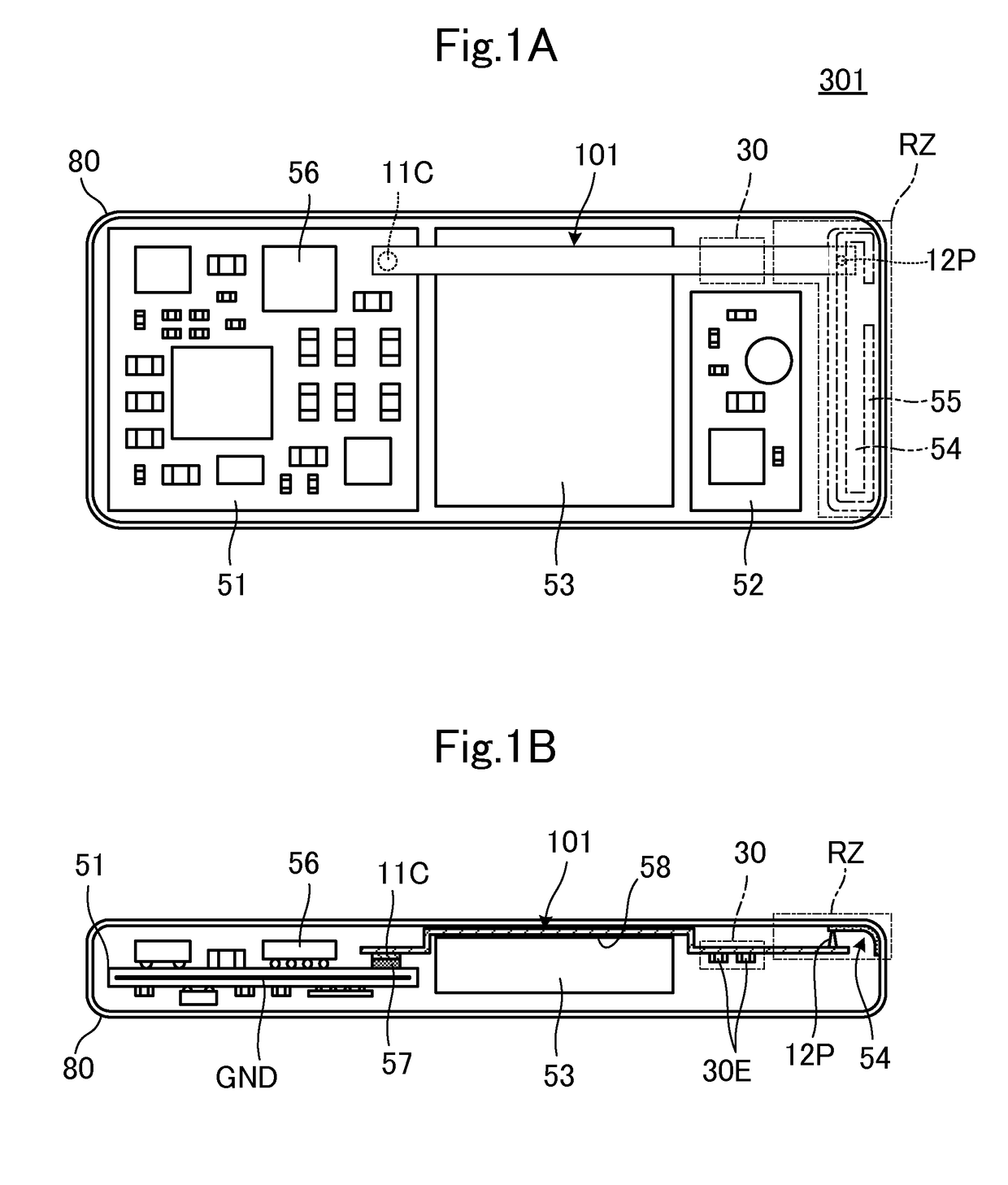
[0037]FIG. 1A is a diagram illustrating a communication terminal apparatus 301 including a signal line module according to a first preferred embodiment of the present invention in a state in which the lower casing (casing on a display panel side) has been removed, i.e., the structure of the inside of a communication terminal apparatus on the upper casing. The communication terminal apparatus 301 preferably is a smart phone supporting a cellular communication system such as GSM (registered trademark). Note that, a radiation board 54 that is attached to the inner surface of the lower casing is illustrated after detaching it from the lower casing. FIG. 1B is a longitudinal sectional view of the communication terminal apparatus 301.

[0038]Printed wire boards 51 and 52, a battery pack 53, and the like are housed in a casing 80. A plurality of electronic components including an RFIC 56 that includes a communication circuit are mounted on the printed wire board 51. A camera module and other...

second preferred embodiment

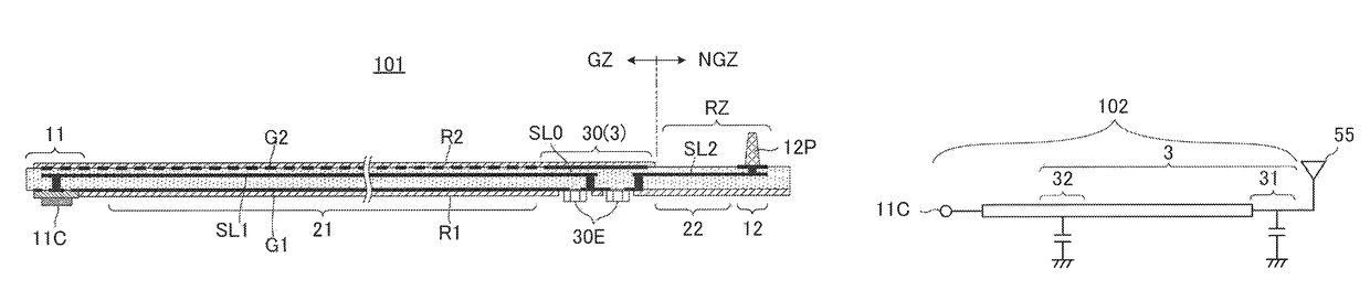
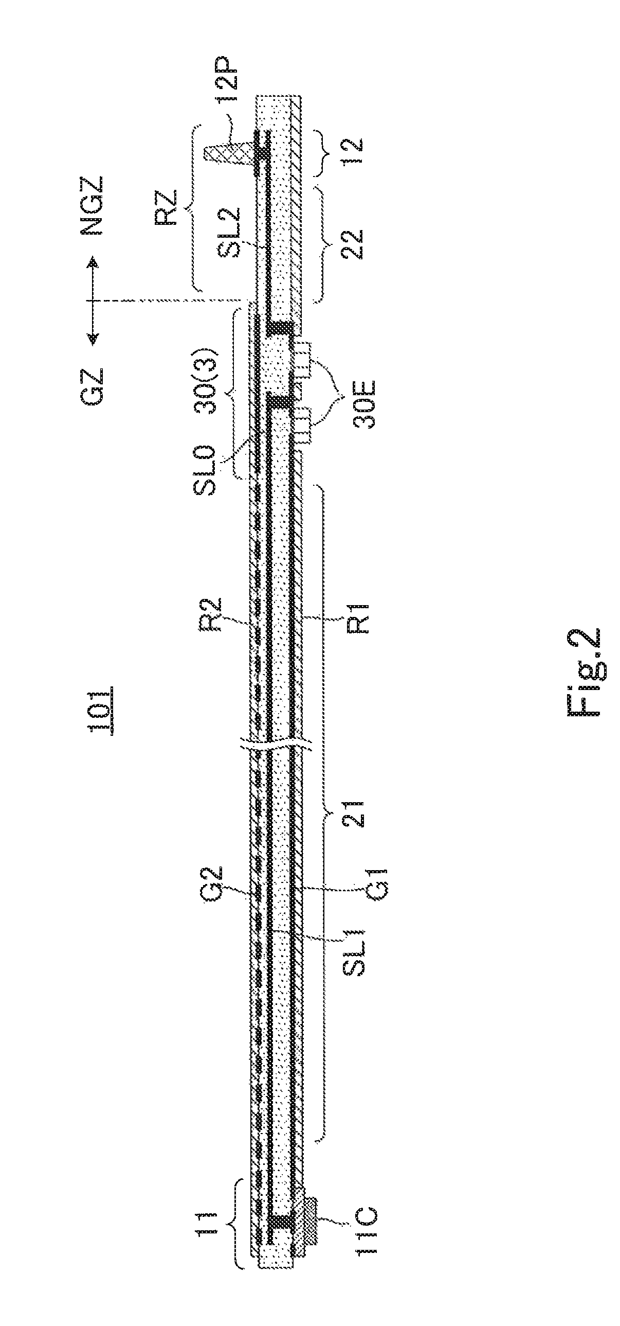
[0061]FIG. 4 is a longitudinal sectional view of a signal line module 102 according to a second preferred embodiment of the present invention. The connector 11C is provided in the first connection portion 11, and the connection pin 12P is provided in the second connection portion 12. The first connection portion 11, the first high-frequency line portion 21, and a first matching circuit portion 31 are provided in the ground zone GZ in which a ground conductor is located. The second high-frequency line portion 22, and the second connection portion 12 are provided in the non-ground zone NGZ in which no ground conductors are located. Unlike the example illustrated in FIG. 2, the first matching circuit portion 31 and a second matching circuit portion32 are provided and these matching circuit portions are defined by conductor patterns.

[0062]FIG. 5 is an exploded perspective view of the first matching circuit portion 31 and the second matching circuit portion 32. The first matching circuit...

third preferred embodiment

[0066]FIG. 10A is a diagram illustrating a communication terminal apparatus 303, including a signal line module 103 according to a third preferred embodiment of the present invention, in a state in which the lower casing (display-panel-side casing) has been removed, i.e., illustrating the internal structure of the main portions on the upper casing side. Note that the radiation board 54 that is attached to the inner surface of the lower casing is illustrated after detaching it from the lower casing. FIG. 10B is a longitudinal sectional view of the main portions of the communication terminal apparatus 303.

[0067]The radiation element 55 is provided on the radiation board 54. The connection pin 12P and a short pin 12PS are in contact with and electrically connected to predetermined positions of the radiation element 55. The termination end of the signal line SL is connected to the feeding point of the radiation element 55 through the connection pin 12P, such that feeding is performed. T...


PUM


Abstract

In a signal line module and a communication terminal apparatus, a first connection portion connected to a feeding circuit, a second connection portion connected to a radiation element, a first high-frequency line portion, a second high-frequency line portion, and a matching circuit portion defining all of or a portion of a first matching circuit are integrally provided in a multilayer body including a plurality of base material layers. The first connection portion, the first high-frequency line portion, and the matching circuit portion are in a ground zone superposed with a ground conductor, when viewed in plan in a stacking direction of the multilayer body, and the second high-frequency line portion and the second connection portion are in a non-ground zone. The second high-frequency line portion and the second connection portion, together with the radiation element, operate as a radiation portion.

Description

BACKGROUND OF THE INVENTION[0001]1. Field of the Invention[0002]The present invention relates to a signal line module, in which functionality has been added to a signal line, and to a communication terminal including such a signal line module.[0003]2. Description of the Related Art[0004]To date, communication terminal apparatuses such as cellular phones have become more compact and functional. Hence, due to restrictions in positions at which various electronic components are arranged in a communication terminal apparatus, a feeding circuit device such as an RFIC chip needs to be placed in a position spaced apart from a radiation element in some cases. An example configuration in such a case is disclosed in, for example, Japanese Unexamined Patent Application Publication No. 2006-325093.[0005]FIG. 14 is a schematic configuration diagram of a communication terminal apparatus disclosed in Japanese Unexamined Patent Application Publication No. 2006-325093. Here, a substrate 2 including ...

Claims


Application Information

Patent Timeline
Patent Type & Authority Patents(United States)
IPC IPC(8): H01Q5/335H01Q9/26H01P3/08H01Q9/42H01Q1/48H01Q1/24
CPCH01Q5/335H01P3/085H01Q1/243H01Q9/26H01Q9/42
Inventor ISHIZUKA, KENICHIKATO, NOBORU
Owner MURATA MFG CO LTD
Why Eureka
Try Eureka