Wireless communication device and marginal transmission power determining method

a technology of transmission power and wireless communication device, which is applied in the direction of power management, transmission monitoring, instruments, etc., can solve the problems of increasing transmission power, unstable operation of wireless communication device, and reducing the voltage value of power to be supplied to the wireless communication device, so as to increase the transmission power (transmission output) quickly

Inactive Publication Date: 2011-02-08
GE TECH DEV INC GETD
View PDF13 Cites 0 Cited by
  • Summary
  • Abstract
  • Description
  • Claims
  • Application Information

AI Technical Summary

Benefits of technology

[0008]The present invention has been implemented to solve the foregoing problem, and has an object to provide a wireless communication device and a marginal transmission determining method that can increase transmission power (transmission output) rapidly while suppressing the consumption current of the wireless communication device to a predetermined range corresponding to a prescribed current value.
[0010]According to the present invention, the transmission power can be increased up to the first marginal transmission power under the condition that the inrush current is within the predetermined range, and then the transmission power can be increased at a small rate (degree). Therefore, the transmission power can be rapidly increased while suppressing the consumption current of the wireless communication device within a predetermined range corresponding to a predetermined current value.
[0013]According to the present invention, the first marginal transmission power is determined for every transmission power before the increase, and thus even when the transmission power before the increase is equal to any value, the transmission power can be rapidly increased while the consumption current of the wireless communication device can be suppressed within the predetermined range corresponding to a predetermined current value.

Problems solved by technology

However, there are some host equipment that cannot keep the standardized voltage when the current input to the wireless communication device increases to a predetermined current value or more, which means that the voltage value of power to be supplied to the wireless communication device is reduced.
However, the recent wireless communication devices have a tendency to have advanced multiplexing of communications and thus the reception power required to carry out demodulation and decoding is increased, which increases the transmission power.
At this time, the voltage value of power supplied to the wireless communication device is lowered as described above, so that the operation of the wireless communication device is unstable or reset occurs due to voltage drop.
However, if the transmission power is increased at such a speed that no inrush current flows as described above, it would take a long time until the transmission power increasing processing for greatly increasing the transmission power of the wireless communication device is completed.

Method used


Image

  • Wireless communication device and marginal transmission power determining method
  • Wireless communication device and marginal transmission power determining method
  • Wireless communication device and marginal transmission power determining method

Examples


embodiment 1

[0026]A first embodiment according to the present invention will be described with reference to the accompanying drawings.

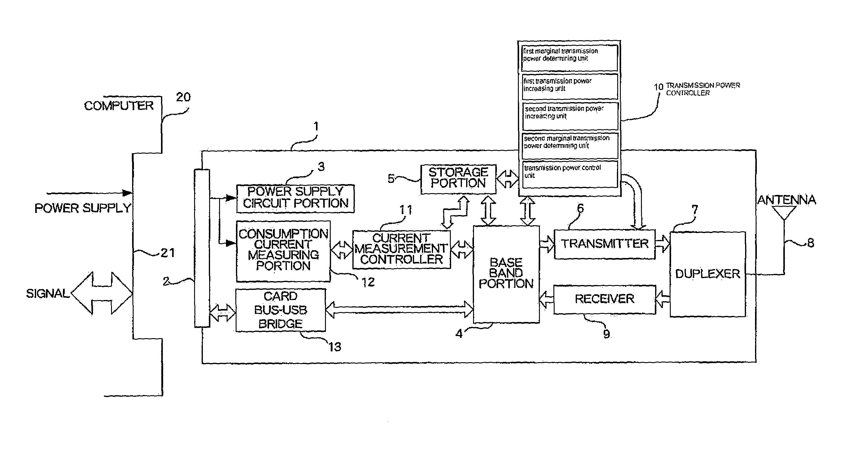
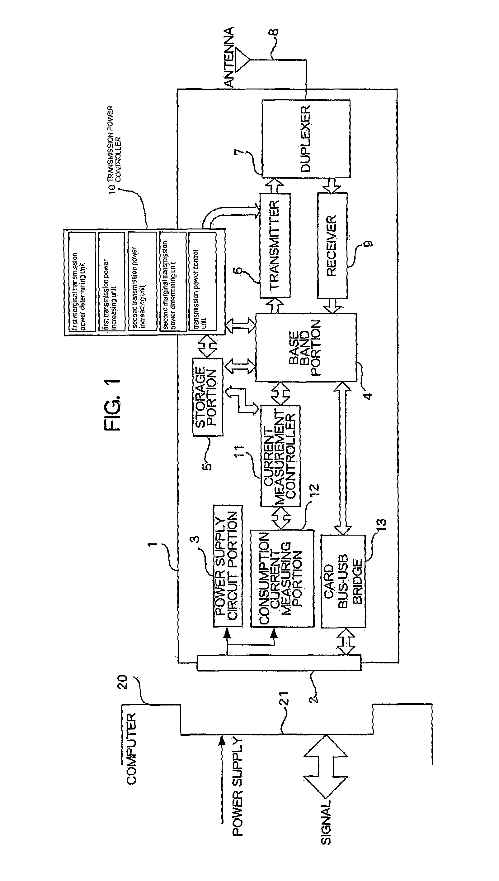
[0027]FIG. 1 is a diagram showing the system construction of a PC card terminal device according to an embodiment of the present invention. As shown in FIG. 1, the PC card terminal device 1 is a wireless communication device functionally including a card bus connector 2, a power supply circuit portion 3, a base band portion 4, a storage portion 5, a transmitter 6, a duplexer 7, antenna 8, a receiver 9, a transmission power controller 10, a current measurement controller 11, and a consumption current measuring portion 12.

[0028]The PC card terminal device 1 is mounted in a card slot 21 of a computer 20 serving as host equipment through the card bus connector 2, and it is supplied with power from the computer 20 as described later and also carries out reception / transmission of signals. The PC card terminal device 1 relays reception / transmission of signals between th...

embodiment 2

[0069]A second embodiment according to the present invention will be described with reference to the drawings.

[0070]The system construction of the PC card terminal device 1 according to the second embodiment is the same as the first embodiment described with reference to FIG. 1. In the second embodiment, the transmission power control processing and the marginal power determining processing are different from those of the first embodiment. Specifically, in the first embodiment, only the first marginal power when the transmission power is increased from the transmission power of zero is determined. However, in the second embodiment, the first marginal power when the transmission power is increased from any transmission power is determined. Therefore, according to the second embodiment, the storage portion 5 stores a first marginal power storage table for storing the present transmission power and the first marginal power in association with each other for every computer 20. The margi...


PUM


Abstract

A PC card terminal device operates while supplied with power from a computer in which the PC card terminal device is mounted. A transmission power controller determines a first marginal transmission power, and increases the transmission power of the PC card terminal device up to the first marginal transmission power, and further increases the transmission power increased to the first marginal transmission power at an increasing rate smaller than the increasing rate of the above-mentioned increase.

Description

BACKGROUND OF THE INVENTION[0001]The present invention relates to a wireless communication device and a marginal transmission power determining method.[0002]A card type wireless communication device has recently become known. Such a card type wireless communication device is mounted in host equipment such as a note-book size personal computer or the like, and used for wireless communication of the host equipment.[0003]The card type wireless communication device as described above has no power source and operates by using power supplied from the host computer. The host equipment supplies power with a standardized voltage value (for example, 3.3V±0.3V in PC Card Standard). Current input from the host equipment to the wireless communication device (consumption current of the wireless communication device) becomes larger as the power (output) of the wireless communication device becomes larger. However, there are some host equipment that cannot keep the standardized voltage when the cur...

Claims


Application Information

Patent Timeline
Patent Type & Authority Patents(United States)
IPC IPC(8): H04B7/00H04W52/04
CPCH04B1/3816H04W52/04G06F1/26G06F13/00G06K7/00G06F15/00H04W52/146H04W52/367
Inventor NAKAYAMA, SHUSUKE
Owner GE TECH DEV INC GETD
Why Eureka
Try Eureka