Implement steerable track assembly with pivoting steering actuator

a technology of steering actuator and track assembly, which is applied in the direction of trailer steering, steering without deflector, vehicle components, etc., can solve the problems of increasing manufacturing and production costs, and affecting reliability

Active Publication Date: 2017-06-27
BLUE LEAF I P INC
View PDF26 Cites 13 Cited by
  • Summary
  • Abstract
  • Description
  • Claims
  • Application Information

AI Technical Summary

Problems solved by technology

Use of the complex linkage systems in the track assemblies may thus increase manufacturing and production costs and be detrimental in terms of reliability due to employing a number of moving components.

Method used


Image

  • Implement steerable track assembly with pivoting steering actuator
  • Implement steerable track assembly with pivoting steering actuator
  • Implement steerable track assembly with pivoting steering actuator

Examples


Embodiment Construction

[0027]One or more specific embodiments of the present disclosure will be described below. In an effort to provide a concise description of these embodiments, all features of an actual implementation may not be described in the specification. It should be appreciated that in the development of any such actual implementation, as in any engineering or design project, numerous implementation-specific decisions must be made to achieve the developers' specific goals, such as compliance with system-related and business-related constraints, which may vary from one implementation to another. Moreover, it should be appreciated that such a development effort might be complex and time consuming, but would nevertheless be a routine undertaking of design, fabrication, and manufacture for those of ordinary skill having the benefit of this disclosure.

[0028]When introducing elements of various embodiments of the present disclosure, the articles “a,”“an,”“the,” and “said” are intended to mean that th...


PUM


Abstract

A work vehicle includes left and right track assemblies, each track assembly including a main frame, a pivot member, a pivot shaft coupled to the pivot member, and an actuator coupled between the pivot shaft and the main frame. Each track assembly is configured to permit pivotal steering movement, pivotal pitch movement, and pivotal camber movement. The actuator of each track assembly is coupled to the respective main frame at one end of the actuator, and at an opposite end of the actuator to an actuator anchor via a self-aligning bearing arrangement to permit transmission of steering forces while enabling pivotal movement of the respective track assembly.

Description

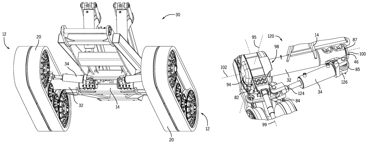
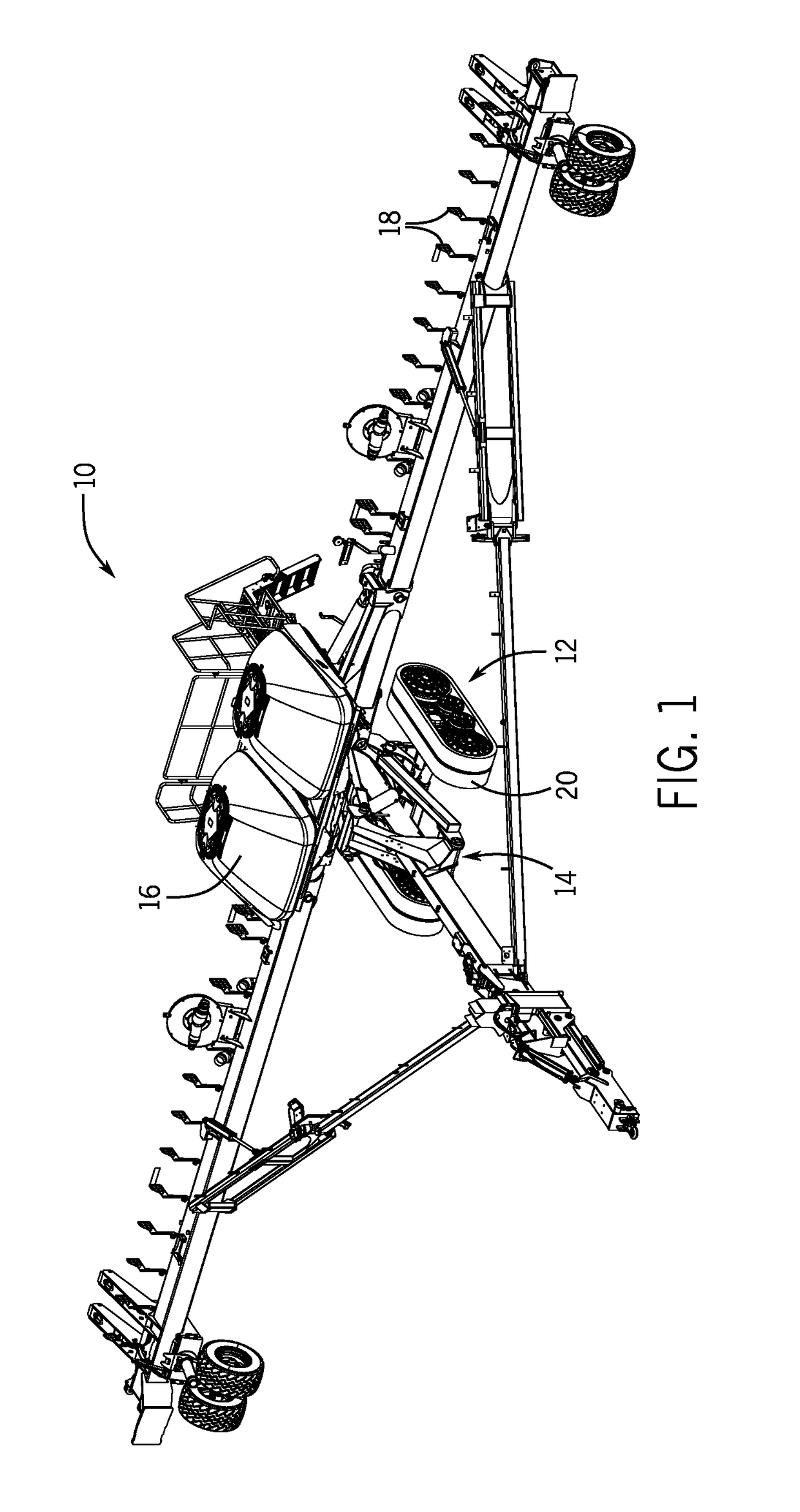
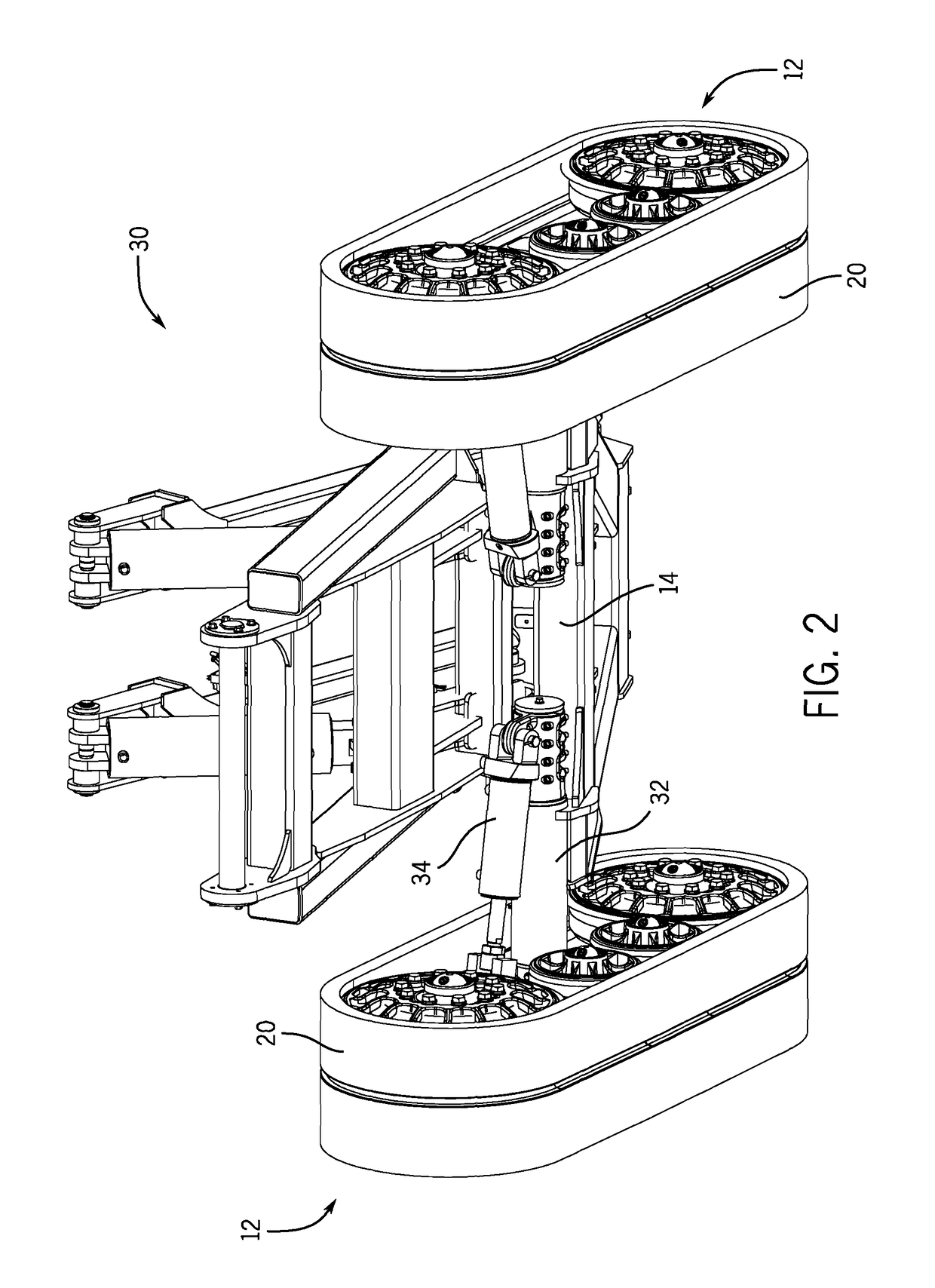
BACKGROUND[0001]The present disclosure relates generally to work vehicles, such as agricultural implements. In particular, the present disclosure relates to a work vehicle with a track assembly that includes an actuator that enables steering and maintains a steering angle of the track assembly throughout the oscillation range of motion of the track assembly.[0002]Track assemblies in work vehicles may use complex linkage systems in order for the track assemblies to rotate and steer as desired by an operator. Use of the complex linkage systems in the track assemblies may thus increase manufacturing and production costs and be detrimental in terms of reliability due to employing a number of moving components.BRIEF DESCRIPTION[0003]Certain embodiments commensurate in scope with the present disclosure are summarized below. These embodiments are not intended to limit the scope of the disclosure, but rather these embodiments are intended only to provide a brief summary of possible forms of...

Claims


Application Information

Patent Timeline
Patent Type & Authority Patents(United States)
IPC IPC(8): B62D55/065B62D55/084B62D55/32B62D55/116
CPCB62D55/084B62D55/0655B62D55/116B62D55/32B62D11/20B62D13/00B62D55/02
Inventor PRICKEL, MARVIN A.PRODDUTURI, SHIVAKUMARLYKKEN, TOMZACH, DAVID ALLEN
Owner BLUE LEAF I P INC
Why Eureka
Try Eureka