
Coin discrimination apparatus

a technology of discrimination apparatus and coins, applied in coin testing, paper-money testing devices, instruments, etc., can solve the problems of dispersion or variation of data obtained from the connecting portion, degradation of discrimination accuracy of bimetallic coins, etc., and achieve the effect of accurately discriminating the denomination and authenticity of coins

Active Publication Date: 2017-07-11
ASAHI SEIKO CO LTD
View PDF48 Cites 1 Cited by
  • Summary
  • Abstract
  • Description
  • Claims
  • Application Information

AI Technical Summary

Benefits of technology

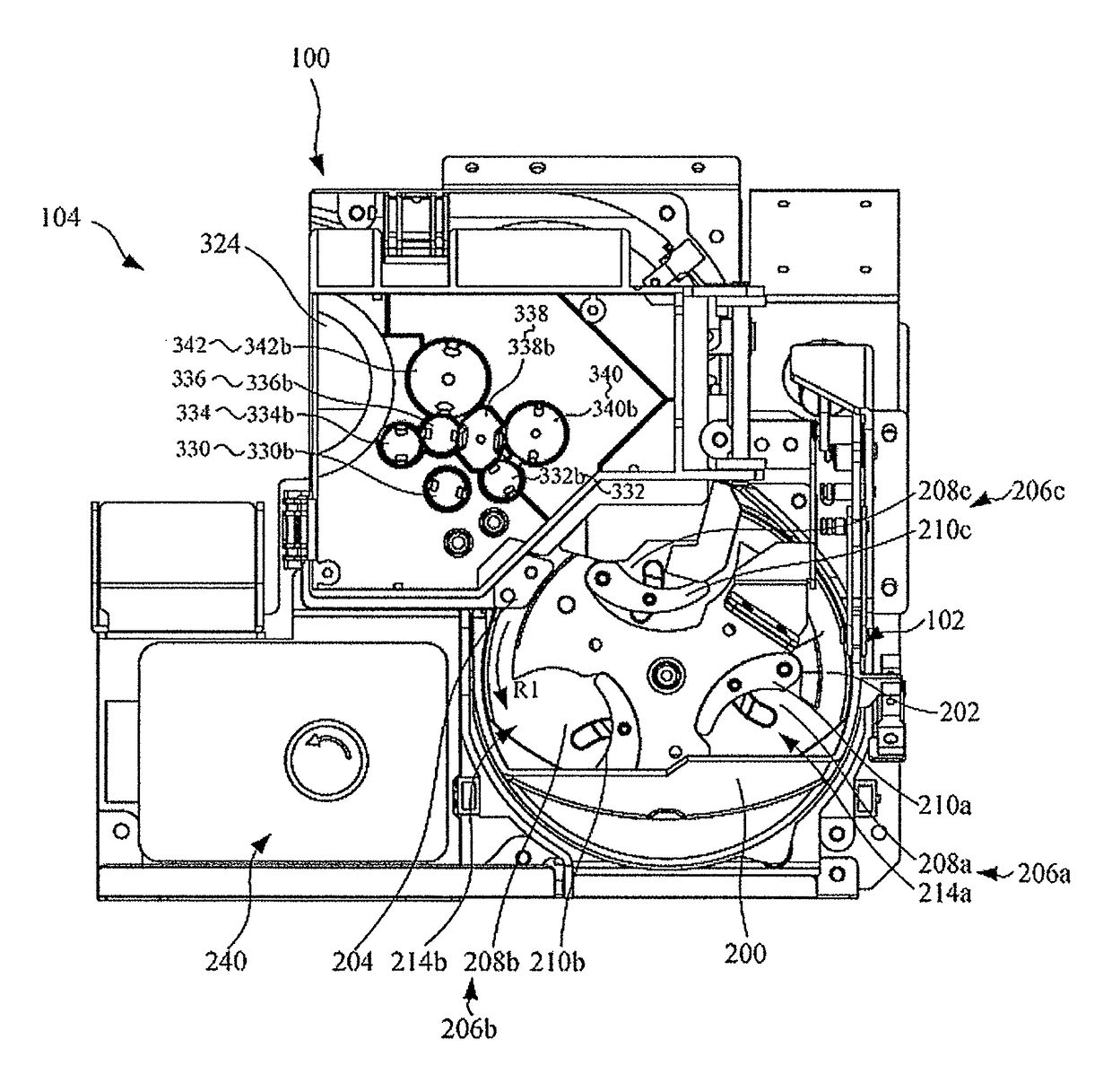
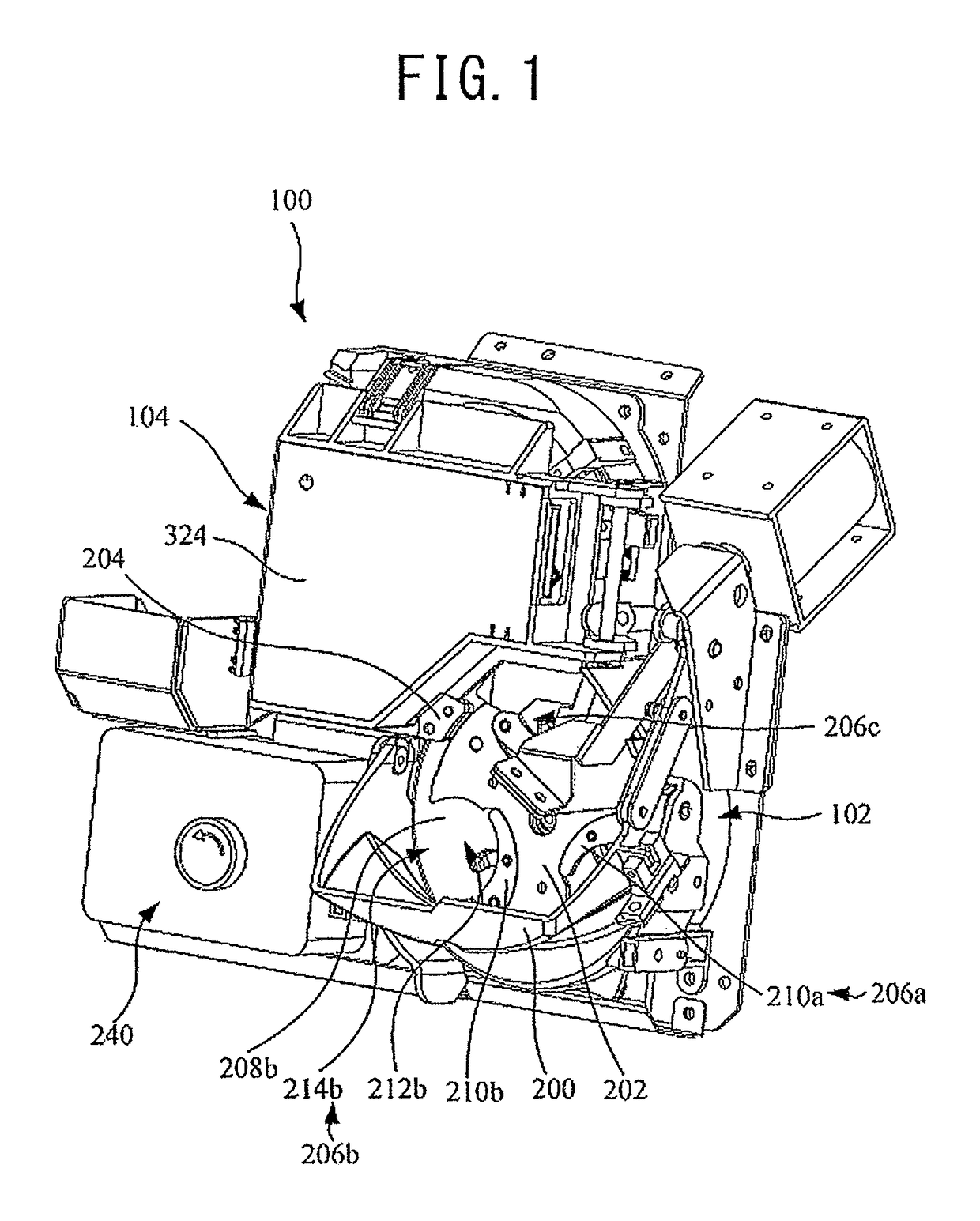
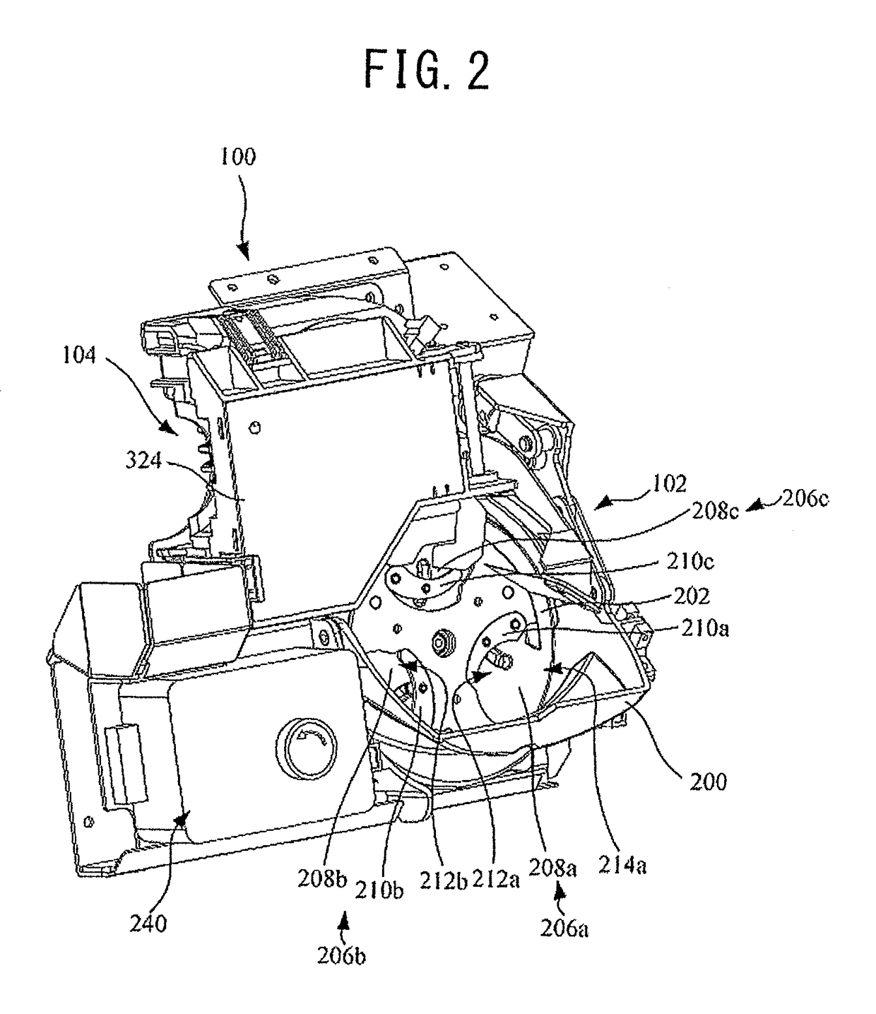
This patent aims to solve the problem of prior art coin denomination discrimination apparatuses by providing a coin discrimination apparatus that can accurately identify the denomination and authenticity of coins, even if they are bimetallic coins. The present invention achieves this by keeping the positional relationships between the coins the same for all coins carried, allowing for accurate detection of physical characteristics about the coins' peripheral and core parts. This results in higher accuracy in discriminating the denomination and authenticity of the coins compared to the case where additional physical characteristics are not obtained. Even if dust or rubbish is attached on the coin detection sensors, the invention ensures high accuracy in discriminating the denomination and authenticity of the coins. Additionally, the invention includes multiple coin detection sensors that provide physical characteristics about the diameter of the coin, allowing for more detailed discrimination of the coin's denomination and authenticity.

Problems solved by technology

Because the connecting portion contains some structural unevenness, the data obtained from the connecting portion is likely to include dispersion or variations.
Accordingly, the data obtained from the connecting portion by the material sensor and the data obtained from the connecting portion by the thickness sensor also will include dispersion or variations, which raises a problem of degradation in discrimination accuracy of bimetallic coins.

Method used


Image

  • Coin discrimination apparatus
  • Coin discrimination apparatus
  • Coin discrimination apparatus

Examples


Embodiment Construction

[0047]Reference will now be made in detail to the preferred embodiments of the invention which set forth the best modes contemplated to carry out the invention, examples of which are illustrated in the accompanying drawings. While the invention will be described in conjunction with the preferred embodiments, it will be understood that they are not intended to limit the invention to these embodiments. On the contrary, the invention is intended to cover alternatives, modifications and equivalents, which may be included within the spirit and scope of the invention as defined by the appended claims. Furthermore, in the following detailed description of the present invention, numerous specific details are set forth in order to provide a thorough understanding of the present invention. However, it will be obvious to one of ordinary skill in the art that the present invention may be practiced without these specific details. In other instances, well known methods, procedures, components, an...


PUM


Abstract

A coin discrimination apparatus capable of discriminating the denomination and authenticity of coins including bimetallic coins. A first coin detection sensor, located near a guide, obtains a physical characteristic of a peripheral part of a coin moved on a carrying path. A second coin detection sensor, located apart from the guide, obtains a physical characteristic about a central part of the coin. A third coin detection sensor, located on a downstream side of respect to the first sensor, obtains a physical characteristic about the peripheral part of a coin. A fourth coin detection sensor, located downstream of the second sensor and apart from the guide, obtains a physical characteristic about a central part of the coin. An additional physical characteristic about the peripheral part of the coin is obtained by cooperation of the second and third sensors when the coin reaches the third sensor.

Description

BACKGROUND OF THE INVENTION[0001]1. Field of the Invention[0002]The present invention relates to a coin discrimination apparatus and more particularly, to a coin discrimination apparatus that makes it possible to discriminate the denomination and authenticity of coins accurately even if they are bimetallic coins.[0003]The term “coin” used in this specification means widely coins as a currency, tokens, medals, and so on, which may have any shape such as circular and polygonal ones.[0004]2. Description of Related Art[0005]Conventionally, as a prior art, a coin denomination discrimination apparatus is known, as disclosed, for example, in the Japanese Patent No. 4780494 (see FIGS. 2 to 6 and Paragraphs 0026 to 0040). This apparatus comprises a slide base made of a non-magnetic material, a rotator made of a non-magnetic material and formed adjacent to the slide base in such a way as to be rotated in a plane parallel to the slide base, a reference guide formed outside a rotation path of t...

Claims


Application Information

Patent Timeline
Patent Type & Authority Patents(United States)
IPC IPC(8): G07D7/00G07D5/02G07D3/12G07D3/14G07D5/08
CPCG07D5/02G07D3/128G07D3/14G07D5/08G07D2205/00
Inventor OHTOMO, HIROSHI
Owner ASAHI SEIKO CO LTD
Learn More