Method and device for monitoring biomechanical properties of the eye

a biomechanical and eye technology, applied in the direction of tonometers, etc., can solve the problems of burdensome and expensive, unable to adapt and periodically adjust the system, etc., and achieve the effect of less calibration efforts

Active Publication Date: 2017-08-08
TISSOT MEDICAL RES
View PDF14 Cites 0 Cited by
  • Summary
  • Abstract
  • Description
  • Claims
  • Application Information

AI Technical Summary

Benefits of technology

[0009]Therefore it is an object of the present invention to provide a method and device which require less calibration efforts.

Problems solved by technology

However, the requirement of an adaptation and periodical recalibration of the system remains, which is burdensome and expensive.

Method used


Image

  • Method and device for monitoring biomechanical properties of the eye
  • Method and device for monitoring biomechanical properties of the eye
  • Method and device for monitoring biomechanical properties of the eye

Examples


example 1

[0058]In order to determine the characteristic values of the hysteresis curve 29 of FIG. 5, it is considered that the acceleration values during opening (aopen) and closing (aclose) of the lid can be derived from the delay between occurrence of maximal force, corresponding to the closed lid, and the time when the force is zero again, i.e. the lid is opened to a degree that the knob 14 no longer exerts a sensible force on the cornea. As explained above, the indentation depth H is then accessible by interpolating the position of the lid using the general equation

slid=½at2v0t+slid0  (6)

with[0059]a: the acceleration of the lid[0060]slid: position of the lid at time t[0061]slid0: position of the lid at t=0: on closing: slid0=0; on opening: slid0=final position of the when closed, i.e. at tIOP0.[0062]t: time[0063]v0: the velocity of the lid at time t=0 defined as the moment when the knob 14 hits the cornea 22 on lid closing; on lid opening: v0=0

[0064]For the application of this equation, ...

example 2

[0103]In order to avoid the computational effort of Example 1, the sensor can be modified the way that at least two segments of distinctly different height Hknob(i), i≧2, are present, Preferably, the segmentation is at least mirror-symmetrical in view of the about mirror-symmetrical movement of the lids.

[0104]FIG. 8 shows an arrangement with two large segments S051 which constitutes the first sensor. Between them two smaller segments S153 are provided, constituting sensor 2. They are characterized by a knob significantly lower than the knob of S0.

[0105]For the data transfer, two antennas 55, 56 are provided for sensor 51 resp. 53, each extending over the whole periphery. However, the antenna / sensor capacitor arrangements are responsive to different frequencies so that the sensors are capable to furnish data independently and without additional measures for avoiding conflicts.

[0106]Besides the antennas 55, 56, FIG. 9 also shows the differing heights Hknob,S0 58 and Hknob,S1 59.

[0107]...

example 3

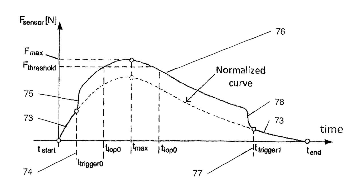
[0114]The knob is provided with a transition 70. In FIG. 12, the transition is a transition to a broader knob shape. In other terms, from the apex 72 to the transition 70, the shape of the knob corresponds to a small knob, and from transition 70 down to the membrane 7, the shape of the basis 71 corresponds to a bigger knob.

[0115]When the knob 14 is pressed on the cornea 22, the signals obtained are those as if the knob has the shape of the small knob (portion 73 in FIG. 13). If the indentation increases, the cornea gets in touch with the transition 70 at time ttrigger0 74. As the contact zone is stepwise increased, also the force signal of the sensor shows a step increase 75. Afterwards, the signal 76 merely corresponds to that of a virtual bigger knob.

[0116]During opening of the eye, the same occurs in the inverse sense at ttrigger1 77: The force signal shows a sharp decay 78 when the cornea no more touches the broader basis 71.

[0117]As shown in FIG. 14, the same effect may be obta...


PUM


Abstract

A contact lens shaped measuring device comprises a sensor having a protrusion towards the cornea. The measuring device is flexible to a degree that it is flattened by a closing eye lid and the protrusion creates an indentation of the cornea. The force on the protrusion is measured by the sensor. Applying a constant lid acceleration / deceleration model to the movement of the lid and a mechanical model to the cornea, the tension of the cornea is determined and deduced from the force measured with the lid closed, yielding the true intraocular pressure. In an alternative, the protrusion is characterized by a discontinuity in its shape, or the sensor is subdivided, each subsensor being characterized by a protrusion of different shape. With the values obtained as extrema and at the discontinuity or with different protrusions, the tension of the cornea can be obtained by a (linear) extrapolation.

Description

CROSS REFERENCE TO RELATED APPLICATIONS[0001]The present application is a 35 U.S.C. §371 National Phase conversion of PCT / CH2012 / 000240, filed Oct. 19, 2012, which claims benefit of U.S. application Ser. No. 13 / 277,379, filed Oct. 20, 2011, the disclosure of which is incorporated herein by reference. The PCT International Application was published in the English language.TECHNICAL FIELD OF THE INVENTION[0002]The present invention relates to a method for monitoring biomechanical properties of the eye, more particularly intraocular pressure or characteristics of the cornea, and a device for measuring eye properties of that kind.BACKGROUND OF THE INVENTION[0003]Conventionally, IOP (cf. Glossary) is measured by applanation of the cornea, e.g. by the Goldman applanometer. Devices of this type exert pressure centrally on the cornea up to a predefined applanation and measure the force required. However, due to the central impact on the cornea, a significant dependence on the curvature of t...

Claims


Application Information

Patent Timeline
Patent Type & Authority Patents(United States)
IPC IPC(8): A61B3/16
CPCA61B3/16
Inventor SAURER, ALAINFEHR, JEAN-NOEL
Owner TISSOT MEDICAL RES
Why Eureka
Try Eureka