Weight training assembly

Active Publication Date: 2017-08-15
LO CHIU HSIANG
View PDF16 Cites 24 Cited by
  • Summary
  • Abstract
  • Description
  • Claims
  • Application Information

AI Technical Summary

Benefits of technology

[0008]The primary object of the present invention is to provide a weight training assembly wherein the weights are adjusted and secured by operating a push unit without pulling pins and inserting pins by the users.
[0009]The present

Problems solved by technology

However, the user have to insert and remove the pins when using the weights, and this may not suitable for some us

Method used


Image

  • Weight training assembly
  • Weight training assembly
  • Weight training assembly

Examples


Embodiment Construction

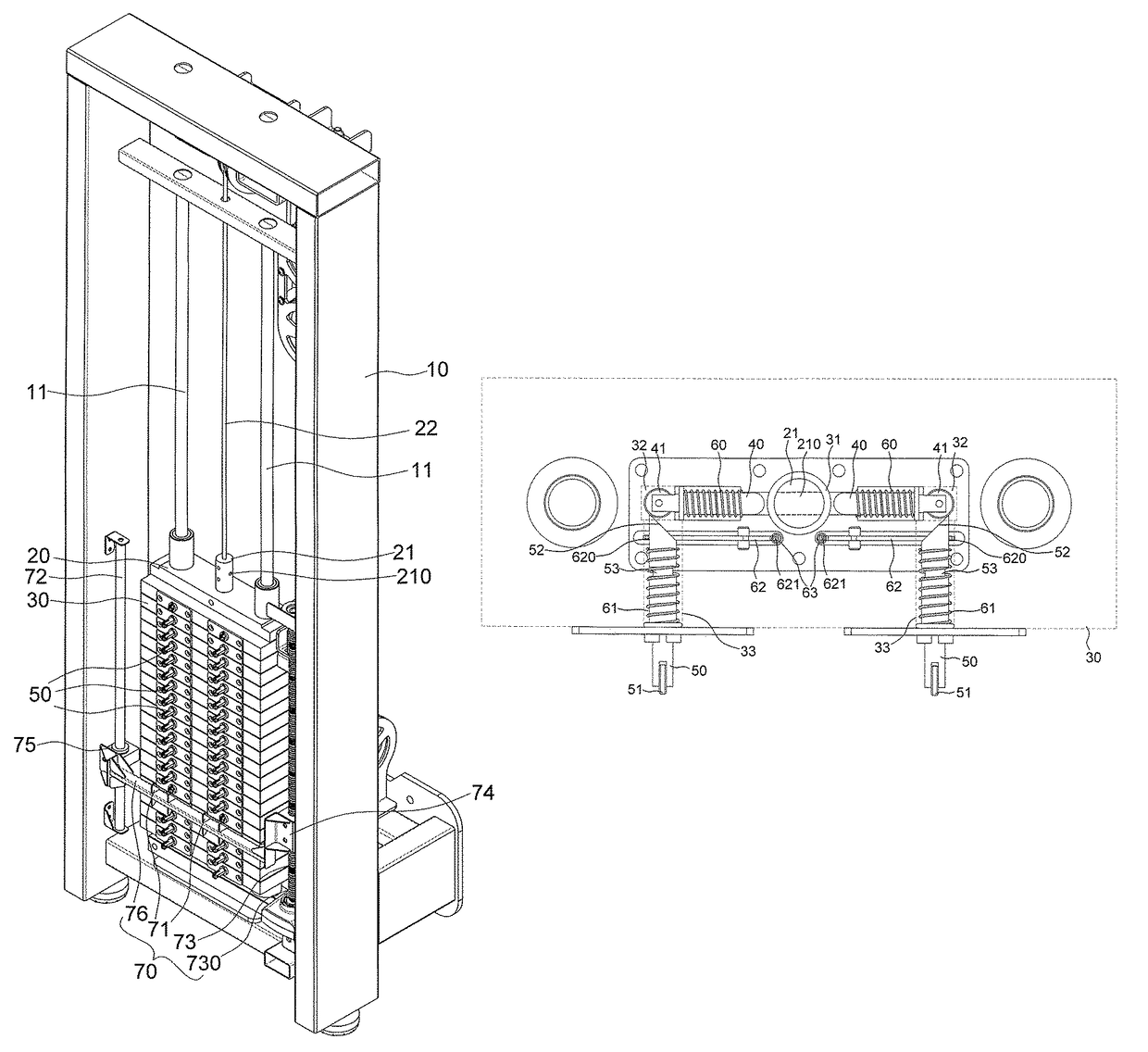
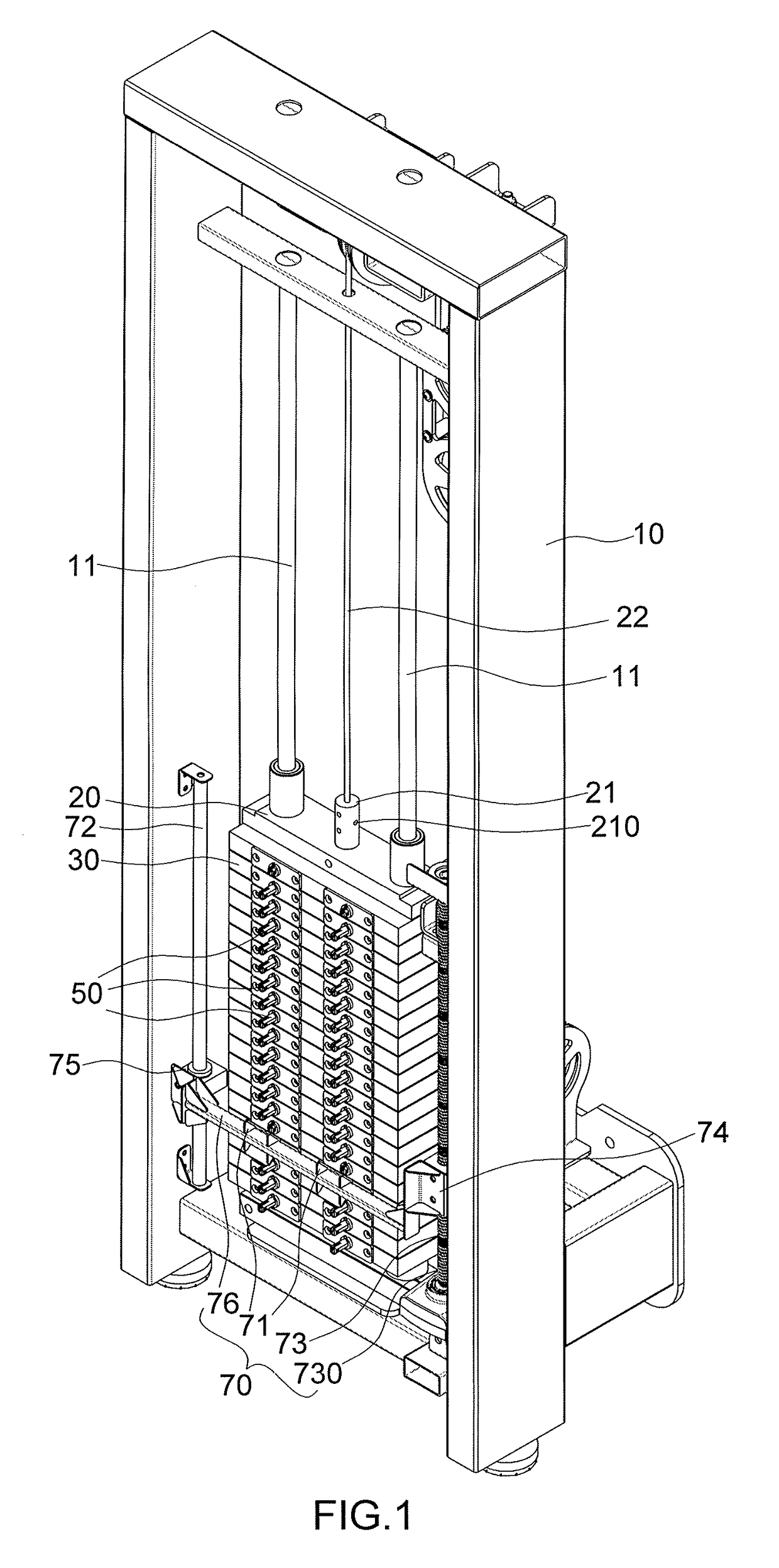
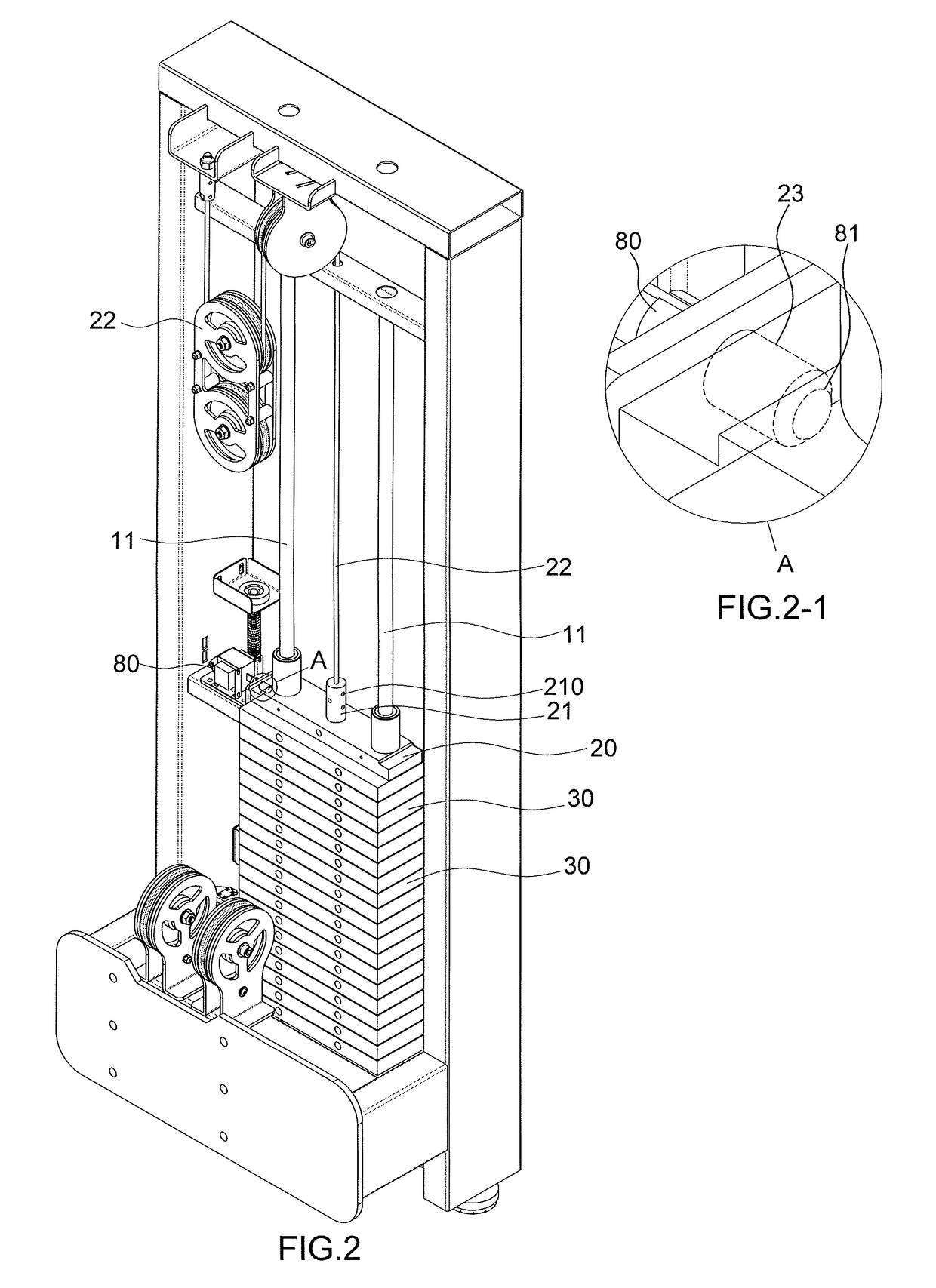
[0020]Referring to FIGS. 1 to 8, the weight training assembly of the present invention comprises a frame 10 having two rails 11 connected thereto. A slide member 20 is movably connected to the rails 11 and has a main rod 21 connected thereto, wherein the main rod 21 is a solid and cylindrical rod, and multiple through holes 210 are defined through the main rod 21.

[0021]A force applying unit 22 is connected to the slide member 20 so that users operate the force applying unit 22 to move the slide member 20 up and down.

[0022]Multiple weights 30 are movably mounted to the rails 11 and each weight 30 has a passage 31 defined axially therethrough, and the main rod 21 extends through the passage 31. Each weight 30 has two transverse holes 32 and two longitudinal holes 33. Each of the transverse holes 32 and the longitudinal holes 33 has a first end and a second end. The two transverse holes 32 are co-axially located in the weight 30 and located on two sides of the passage 31. The two respe...


PUM


Abstract

A weight training assembly includes a frame includes a first rail to which a slide member and multiple weights are connected. The slide member has a main rod with multiple through hole. Each weight has a transverse holes and longitudinal holes, each transverse hole has a pin received therein, and each longitudinal hole has a push rod received therein. A first spring is located between the pin and the weight. A second spring is located between the push rod and the weight. A push unit includes a push member which is located corresponding to the front sides of the weights. When the push member pushes the push rod from the first position to the second position, the pin moves from the third position to the third position and extends through one through hole to lock the weight to the main rod.

Description

BACKGROUND OF THE INVENTION[0001]1. Fields of the Invention[0002]The present invention relates to a weight training assembly, and more particularly, to a weight training assembly with weights locking device.[0003]2. Descriptions of Related Art[0004]The conventional weight training assemblies known to applicant are disclosed in U.S. Pat. Nos. 6,551,223, 6,974,405, and 7,011,609, and generally comprises a rail with a slide and multiple weights slidably mounted to the rail. The slide has a rod connected thereto which is connected with a force applying unit, and multiple holes are defined through the rod. The users operates the force applying unit to move the slide. Each weight has transverse holes and a longitudinal hole, each transverse hole has a pin received therein, and the rod extends through the longitudinal hole. When in operation, the pin of the desired weight extends through the hole of the rod to lock the weight to the rod. When removing the pin from the hole, the weight is m...

Claims


Application Information

Patent Timeline
IPC IPC(8): A63B21/062
CPCA63B21/0628A63B21/063A63B24/0087
Inventor LO, CHIU-HSIANG
Owner LO CHIU HSIANG
Why Eureka
Try Eureka