Tensioning rail, and traction mechanism drive including such a tensioning rail

a technology of traction mechanism and tensioning rail, which is applied in the direction of gearing, belt/chain/gearing, mechanical apparatus, etc., can solve the problems of high level of effort for manufacturing such a guide rail, the guide rail may tilt slightly about a longitudinal axis, and the traction mechanism cannot be jammed in the tensioning rail, etc., to achieve dimensional stability, functional reliability, and convenient and cost-effective manufacturing.

Inactive Publication Date: 2017-09-12
SCHAEFFLER TECH AG & CO KG
View PDF34 Cites 2 Cited by
  • Summary
  • Abstract
  • Description
  • Claims
  • Application Information

AI Technical Summary

Benefits of technology

[0008]It is an object of the present invention to provide a tensioning rail, which is preferably easily and cost-effectively manufacturable as well as dimensionally stable and functionally reliable, for tensioning a continuously revolving traction mechanism. Moreover, and alternate or additional object of the present invention is to provide a traction mechanism drive which includes such a tensioning rail.
[0009]The present invention provides that the tensioning rail includes a guide element for a pivot bearing in the U-shaped profile section. For the U-shaped profile section, the cheeks are spaced apart from one another. A guide element for the pivot bearing in this U-shaped profile section therefore has a particularly effective action against a torque about a longitudinal axis of the tensioning rail. The tensioning rail is therefore particularly robust against tilting about a longitudinal axis of the tensioning rail.

Problems solved by technology

Thus, it is not possible for the traction mechanism to jam in the tensioning rail.
In practice, however, it has been found that, due to the small width of the guide rail in the particular T-shaped profile section and the cross-hole formed there for the pivot bearing, there is a risk that during operation the guide rail may tilt slightly about a longitudinal axis.
The level of effort for manufacturing such a guide rail is therefore very high.

Method used


Image

  • Tensioning rail, and traction mechanism drive including such a tensioning rail
  • Tensioning rail, and traction mechanism drive including such a tensioning rail
  • Tensioning rail, and traction mechanism drive including such a tensioning rail

Examples


Embodiment Construction

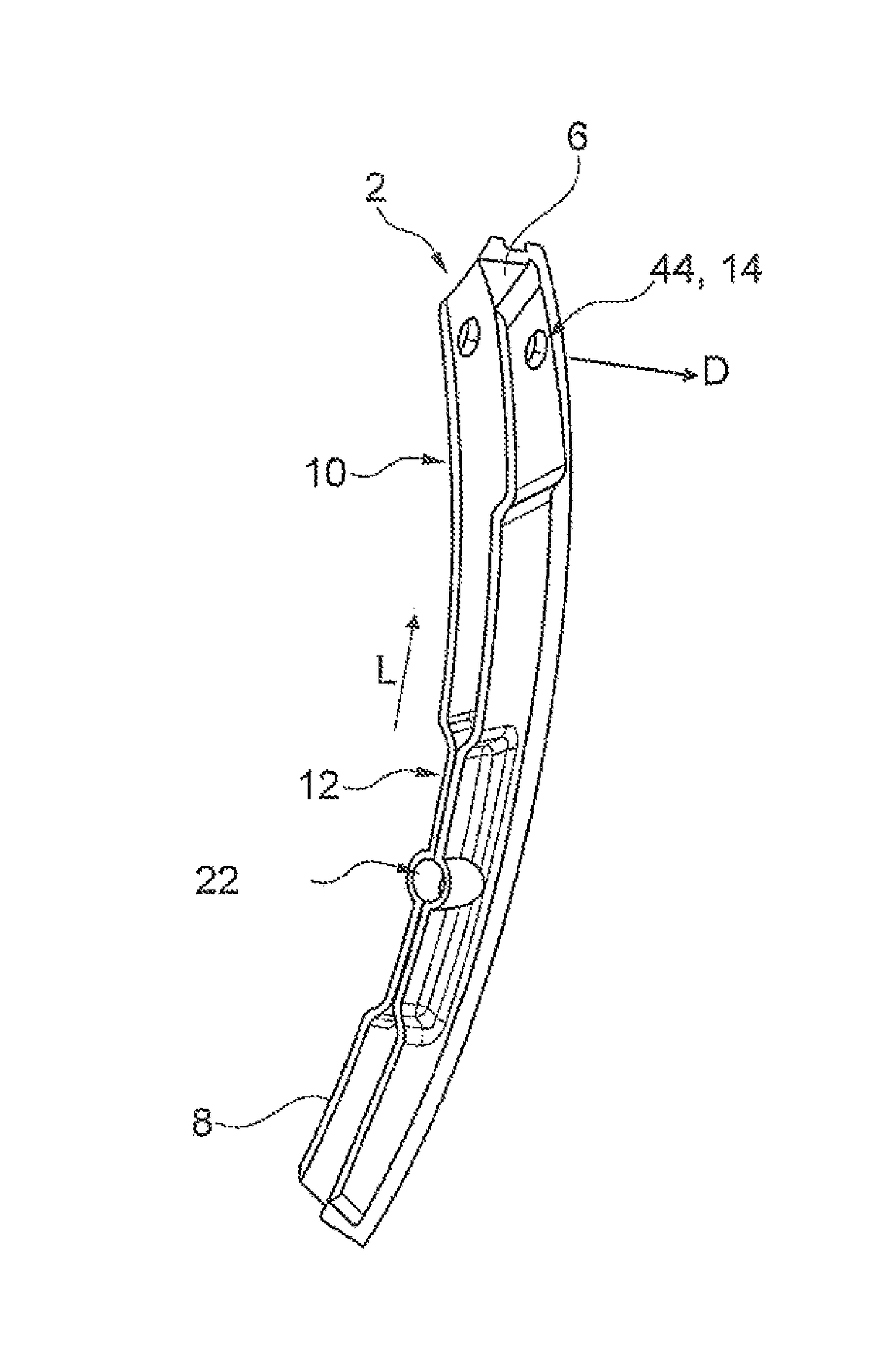
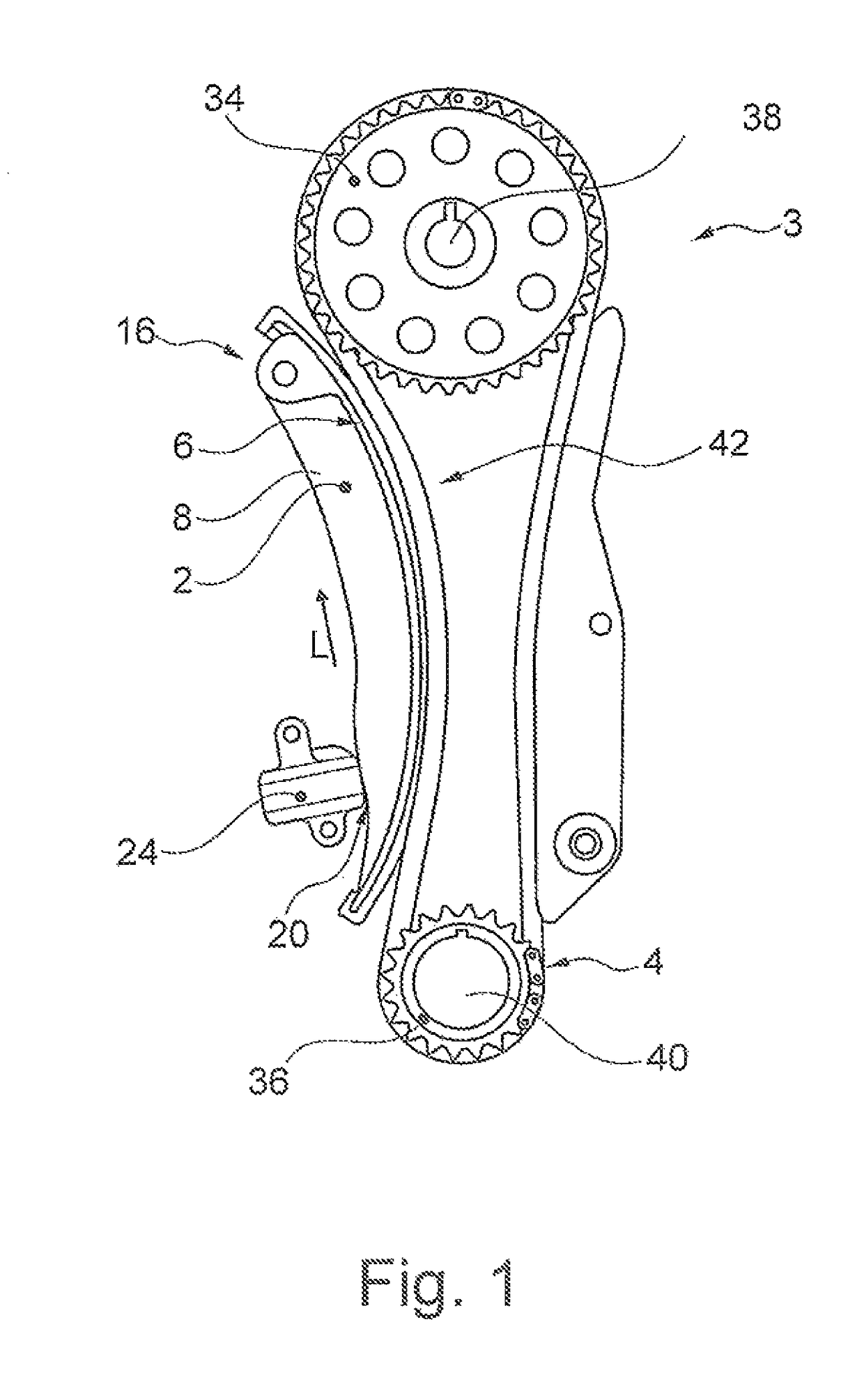
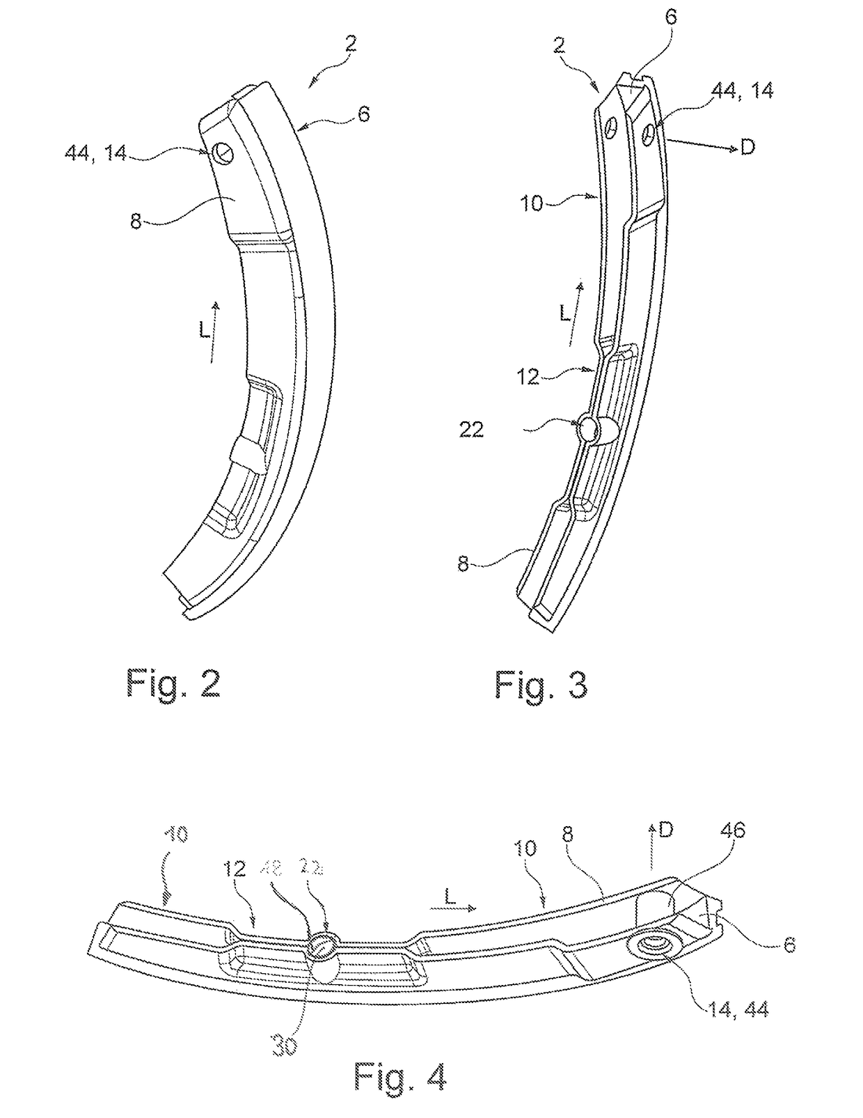
[0027]FIG. 1 shows a traction mechanism drive 3 according to the present invention, including a drive wheel 34 situated on a shaft 32 of an internal combustion engine (not illustrated), and including a drive wheel 36. In principle, multiple drive wheels 34 may be provided. Traction mechanism drive 3 includes a continuously revolving traction mechanism 4 which encompasses drive wheel 34 and the at least one drive wheel 36. Due to traction mechanism 4 which is in engagement with drive wheel 34 and with drive wheel 36, mechanical power may be transferred from drive wheel 34 to drive wheel 36. The same applies for the shafts connected in each case. Traction mechanism 4 is generally designed as a chain or as a belt. If a chain is used, gearwheels are employed as wheels.

[0028]To ensure a secure revolution of traction mechanism 4, it has proven to be advantageous to tension traction mechanism 4. For this purpose, a tensioning rail 2 as illustrated in FIGS. 2 through 4 is pressed against co...


PUM


Abstract

A tensioning rail (2) for tensioning an endlessly circulating tensioner (4) is provided, wherein the tensioning rail (2) for tensioning the ternsioner (4) is curved in a longitudinal direction (L), the tensioning rail (2) has a base wall (6) and two jaws (8) protruding from the base wall (6), and the tensioning rail (2) has at least one U-shaped profiled segment (10) and a T-shaped profiled segment (12), which are each formed by the base wall (6) and the jaws (8), wherein the tensioning rail (2) includes a guiding element (14) for a rotary bearing (16) in the U-shaped profiled segment (10) and a guiding element (18) for a contact bearing (20) in the T-shaped profiled segment (12).

Description

[0001]The present invention relates to a tensioning rail for tensioning a continuously revolving traction mechanism, the tensioning rail for tensioning the traction mechanism being arched in the longitudinal direction, the tensioning rail including a base wall and two cheeks protruding from the base wall, and the tensioning rail including at least one U-shaped profile section and one T-shaped profile section, each of which is formed by the base wall and the cheeks.[0002]Moreover, the present invention encompasses a traction mechanism drive which includes a drive wheel situated on a drive shaft of an internal combustion engine, at least one driving wheel, a continuously revolving traction mechanism which encompasses the drive wheel and the at least one driving wheel, a tensioning rail of the above-mentioned type, and a tensioning device for transmitting a tension force to the tensioning rail.BACKGROUND[0003]Tensioning rails are preferably used for traction mechanism drives of interna...

Claims


Application Information

Patent Timeline
Patent Type & Authority Patents(United States)
IPC IPC(8): F16H7/08F16H7/18F16H7/06F16H7/02
CPCF16H7/08F16H7/02F16H7/06F16H7/18F16H2007/0872F16H2007/0893F16H2007/185
Inventor MOURA, CARLOSALMEIDA, CESARSAYAO, DANIEL DOS ANJOS
Owner SCHAEFFLER TECH AG & CO KG
Why Eureka
Try Eureka