Fan blade for a gas-turbine engine

a gas-turbine engine and fan blade technology, which is applied in the field offan blades, can solve the problems of increased cost of these blades, increased weight and additional costs, and high mechanical load, and achieves the effect of satisfactory high safety requirements, easy and cost-effective manufacturing

Inactive Publication Date: 2006-04-25
ROLLS ROYCE DEUT LTD & CO KG
View PDF13 Cites 31 Cited by
  • Summary
  • Abstract
  • Description
  • Claims
  • Application Information

AI Technical Summary

Benefits of technology

[0005]The present invention, in a broad aspect, provides for the development of a mass-reduced and mechanically highly loadable fan blade for gas-turbine engines which is easily and cost-effectively manufacturable and satisfies high safety requirements.
[0009]With a relatively low and, in particular, easily obtainable weight reduction in a limited area extending from the blade tip, the centrifugal forces and stresses present at the blade root can be reduced considerably or be set optimally. For example, a weight reduction in the tip area of 3 percent enabled the centrifugal forces effective at the blade root to be reduced by 12 percent. The saving of mass only in the tip area by cavities formed from the free face reduces the effective length of the blade mass on the whole, namely in terms of a shortening of the blade, thus reducing the vibration amplitudes and raising the natural frequencies, resulting in considerably lower stress and damage to the fan blades. If several cavities are provided side by side and apart from each other, the reinforcing ribs formed between these cavities contribute to the mechanical strength of the blade tip portion. A further, significant advantage of the proposed fan blade is its simple, cost-effective manufacturability, in particular since the cavity forming process can be included in the normal manufacturing technologies for solid fan blades without any difficulty.

Problems solved by technology

The high weight resulting therefrom significantly increases the costs of these blades and entails high mechanical loads arising from the natural vibrations and the vibration amplitude as well as the centrifugal forces.
This involves a further increase in weight and additional costs.
The methods for the production of such hollow blades described, for example, in U.S. Pat. No. 6,033,186 and U.S. Pat. No. 5,692,881 are, however, very costly.
Particularly with small and medium-power engines, the high costs for such hollow fan blades are not effective in relation to the weight saving obtained and the advantages resulting from such a weight saving.

Method used


Image

  • Fan blade for a gas-turbine engine
  • Fan blade for a gas-turbine engine
  • Fan blade for a gas-turbine engine

Examples


Embodiment Construction

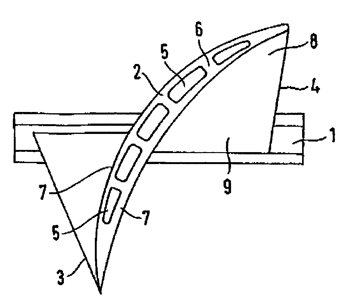
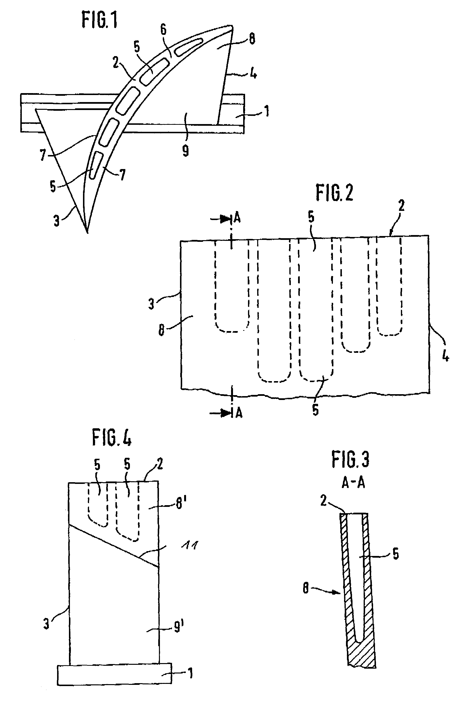
[0018]This detailed description should be read in conjunction with the summary of the invention above. The titanium fan blade shown in FIG. 1 comprises a blade root 1 and a blade tip 2. It has a leading edge 3 and a trailing edge 4. Arranged in the upper third of the fan blade, the blade tip portion 8, are cavities 5 which start out from the blade tip 2 and which are separated by reinforcing ribs 6. The reinforcing ribs 6 and the thickness of the remaining blade wall 7 ensure the stiffness of the fan blade and the required shear stress transfer. The cavities 5 have an essentially rectangular cross-sectional shape. Other shapes, for example round or oval, are also possible. As is shown in FIGS. 2 to 4, the cavities 5 are situated only in the tip area, or approximately in the upper third of the fan blade, with the remaining area, the blade root portion 9, being solid. The contour of the longitudinal axis of the long cavities 5 conforms to the shape of the fan blade. For example, the l...


PUM


Abstract

For material reduction, a fan blade made of solid material for a gas-turbine engine is provided in the area of the blade tip with at least one cavity (5) extending from the face of the blade tip. Thus, apart from the aspect of weight saving, the vibration amplitudes and the centrifugal forces can be reduced considerably and the natural vibration behavior improved in a simple manner, ultimately increasing mechanical strength.

Description

[0001]This application claims priority to German Patent Application DE10301755.0 filed Jan. 18, 2003, the entirety of which is incorporated by reference herein.BACKGROUND OF THE INVENTION[0002]This invention relates to a fan blade in solid material for a gas-turbine engine.[0003]The fan blades are the foremost rotating components of a gas-turbine engine. Besides the inflowing air, these blades are exposed to ingested foreign bodies, such as birds, primarily in the take-off phase. In order to withstand the extremely high loads, in the event of a bird strike for example, the fan blades, which are made of a solid high strength-material, such as titanium or a corresponding alloy for example, must be dimensioned adequately. The high weight resulting therefrom significantly increases the costs of these blades and entails high mechanical loads arising from the natural vibrations and the vibration amplitude as well as the centrifugal forces. Furthermore, the fan protective casings, or fan c...

Claims


Application Information

Patent Timeline
Patent Type & Authority Patents(United States)
IPC IPC(8): F01D5/12F01D5/14F01D5/16F01D5/18F04D29/32F04D29/66
CPCF01D5/147F01D5/16F01D5/18F04D29/324F04D29/668Y10S416/50Y02T50/671Y02T50/673Y02T50/676F01D5/20Y02T50/60
Inventor SCHREIBER, KARL
Owner ROLLS ROYCE DEUT LTD & CO KG
Why Eureka
Try Eureka