Electric machine with a corona shield

a technology of electric machines and corona shields, applied in the field of electric machines, can solve the problems of limiting the establishment of electrical conductivity, disadvantageous reduction process, and adverse effects on the electrical conductivity of the partially hardened corona shields, and achieve the effect of strengthening the adhesion

Inactive Publication Date: 2007-06-28
SIEMENS AG
View PDF7 Cites 35 Cited by
  • Summary
  • Abstract
  • Description
  • Claims
  • Application Information

AI Technical Summary

Benefits of technology

[0037] When repeatedly applying a coating process, the coating may include more than one layer. In particular when coating of a filament or band-shaped substrate is involved, a multiple application of the coating process can be utilized to form an adhesive layer to enhance the adhesion between the electrically conductive coating and the substrate layer or the uncoated filament. Several coats are also advantageous to provide a balance between different thermal expansion coefficients.

Problems solved by technology

While impregnation enables the production of a corona shield, there are many drawbacks associated therewith.
During the impregnation of the electric machine, also called VPI process (Vacuum Pressure Impregnation), the electric conductivity of the partially hardened corona shield is adversely affected and may change.
The need for a reduction process is not only disadvantageous but also limits the establishment of electrical conductivity to only a top layer of the corona shield.
Thus, electric conductivity cannot be realized across the entire cross section.
Moreover, the top layers of the corona shield can get damaged, when the electric conductors, on which the corona shield is attached, are installed, normally by hammering, into the slots of an electric machine.
A drawback of organic binders is their poor resistance to thermal stress which can result in a change of positioning of the electrically conductive materials within the binder so that ultimately the electric conductivity is altered.
Contact between the electrically conducting materials (SiC, soot, graphite) gets lost or at least decreases, causing a reduced conductivity.
The provision of soot is also disadvantageous because it is prone to wear off, as the corona shield is handled, so as to produce rubbings which also adversely affect the electric conductivity.
As a consequence of the required use of organic binder and its limited resistance to thermal stress (up to about 180°), the used materials will be destroyed by partial discharges.
In addition, the electric conductivity is adversely affected by the VPI impregnation process, and, moreover, soot particles or graphite particles are inadvertently carried away by the impregnating resin, thereby contaminating the electrically conductive fillers and the quality of the impregnation.
The use of organic material is also disadvantageous because of the adverse impact of ozone that is produced during partial discharges.
As a result of the destruction of the organic material, partial discharges in the electric machine increase further on the conductors, thereby forming even more ozone that leads to the increasing destruction of the organic material, ultimately causing a breakdown of the electric machine.
The use of organic resin for soaking glass fabrics or polyester fabrics limits, however, the maximum temperature at which the electric machine can operate properly.
The ozone generated by partial discharges also destroys the soot or graphite contained in the organic resin so that the electric conductivity of the corona shield decreases and the organic resin increasingly dissolves, ultimately destroying the corona shield.

Method used


Image

  • Electric machine with a corona shield
  • Electric machine with a corona shield
  • Electric machine with a corona shield

Examples


Embodiment Construction

[0068] Throughout all the Figures, same or corresponding elements are generally indicated by same reference numerals. These depicted embodiments are to be understood as illustrative of the invention and not as limiting in any way. It should also be understood that the drawings are not necessarily to scale and that the embodiments are sometimes illustrated by graphic symbols, phantom lines, diagrammatic representations and fragmentary views. In certain instances, details which are not necessary for an understanding of the present invention or which render other details difficult to perceive may have been omitted.

[0069] reference is made to commonly assigned copending patent application by a different inventive entity, application Ser. No. 11 / 014,632 and entitled “Corona Shield, and Method of Making a Corona Shield”, filed Dec. 16, 2004, the disclosure of which is expressly incorporated herein by reference.

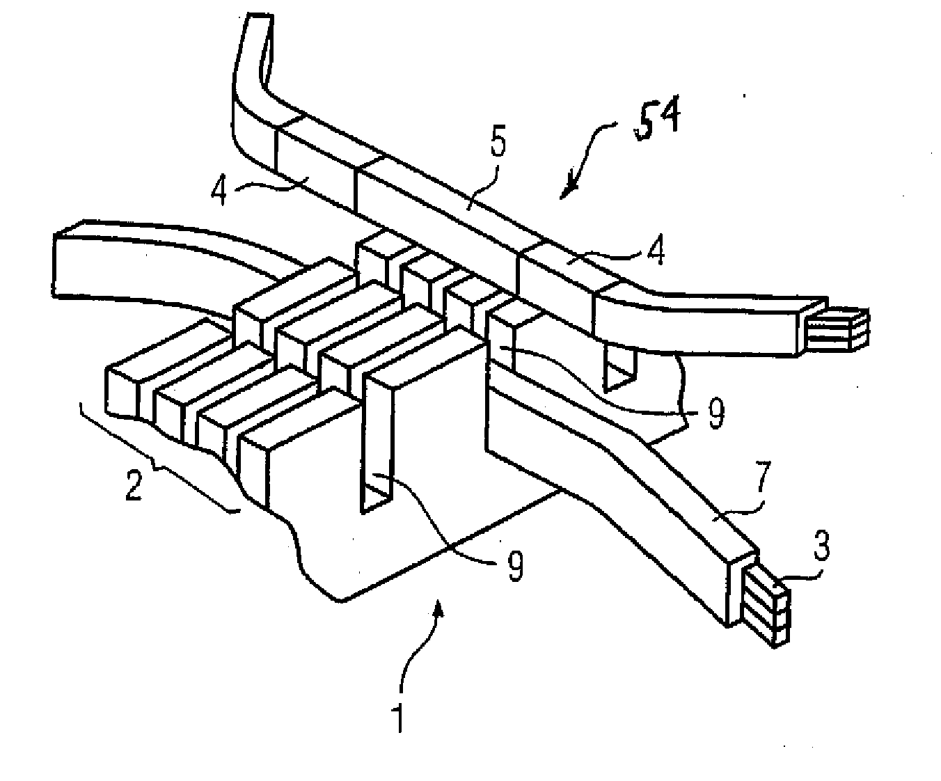
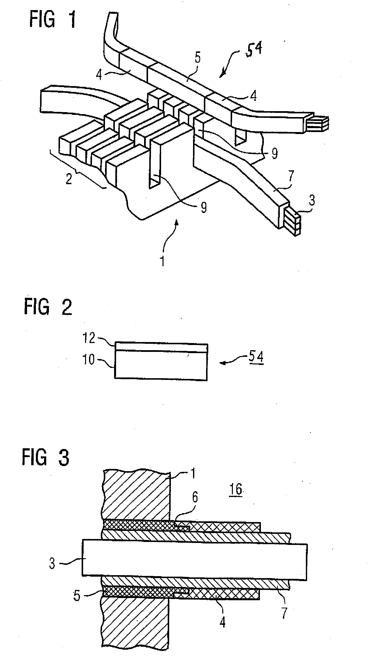
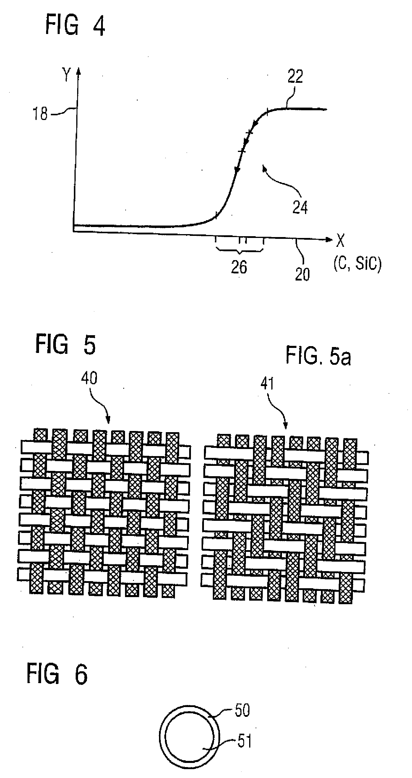
[0070] Turning now to the drawing, and in particular to FIG. 1, there is show...


PUM

PropertyMeasurementUnit
thicknessaaaaaaaaaa
temperatureaaaaaaaaaa
voltagesaaaaaaaaaa

Abstract

An electric machine includes a laminated stator core having slots for receiving a stator winding, and a corona shield for insulating the stator winding. The corona shield includes a substrate; and a coating applied on the substrate, wherein the substrate and the coating are made entirely of inorganic material.

Description

CROSS-REFERENCES TO RELATED APPLICATIONS [0001] This application is a continuation of prior filed copending U.S. application Ser. No. 11 / 014,631, filed Dec. 16, 2004, the priority of which is hereby claimed under 35 U.S.C. §120, and which is a continuation of prior PCT International application no. PCT / DE03 / 01864, filed Jun. 5, 2003, which designated the United States and on which priority is claimed under 35 U.S.C. §120, and which claims the priority of German Patent Application, Ser. No. 102 27 227.1, filed Jun. 18, 2002, pursuant to 35 U.S.C. 119(a)-(d).BACKGROUND OF THE INVENTION [0002] The present invention relates, in general, to an electric machine, and more particularly to an electric machine including a corona shield. [0003] Nothing in the following discussion of the state of the art is to be construed as an admission of prior art. [0004] A typical corona shield includes at least a fabric or a non-woven fabric made of glass or polyester. Examples of fabrics are referred to ...

Claims


Application Information

Patent Timeline
Patent Type & Authority Applications(United States)
IPC IPC(8): B32B5/02G21K1/00H02K15/10
CPCH02K3/40Y10T442/20
Inventor KLAUSSNER, BERNHARDMEYER, CHRISTOPHMUHRER, VOLKERMAURER, ALEXANDERRUSSEL, CHRISTIANSCHAFER, KLAUS
Owner SIEMENS AG
Why Eureka
Try Eureka