Monitoring systems and methods

a technology of monitoring system and monitoring method, applied in the field of monitoring system, can solve the problem that the infrared signatures suggestive of visitors may be misleading, and achieve the effect of secure and convenien

Active Publication Date: 2017-09-19
SKYBELL TECH IP LLC
View PDF213 Cites 228 Cited by
  • Summary
  • Abstract
  • Description
  • Claims
  • Application Information

AI Technical Summary

Benefits of technology

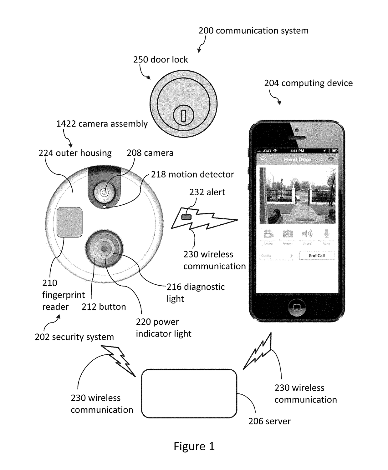
[0014]Various systems can provide a secure and convenient way for a remotely located individual to communicate with a person who is approaching a sensor, such as a proximity sensor or motion sensor, or with a person who rings a doorbell. A doorbell or camera assembly can be located in a doorway, near an entrance, within 15 feet of a door, inside a building, or near a pool.
[0022]An infrared signature that seems to indicate that a visitor is present can be a type of indication. The infrared signature may be of a shape and / or temperature that suggests the infrared signature is from a visitor (i.e., a person). In many cases, infrared signatures suggestive of visitors are actually from visitors, but in some cases, infrared signatures suggestive of visitors may be misleading (and not actually be from visitors). The size of the infrared signature can help the system determine if the visitor is above or below a size threshold. This threshold can be advantageous to enable the system to ignore adults (because adults can likely swim) while not ignoring children (because many children cannot swim).
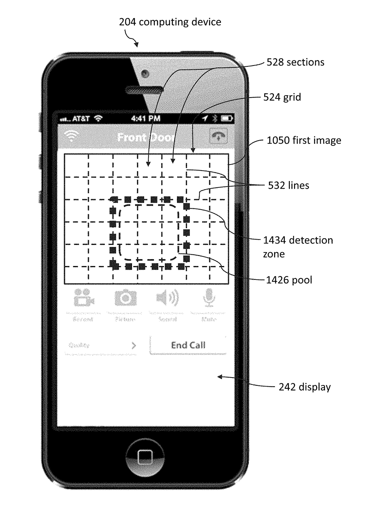
[0033]Some embodiments reduce false positives by preventing the sending of the first alert to the remote computing device until after detecting the second indication in at least two of the sections. Several embodiments cause a second subset of the sections to be included in the first detection zone in response to the first subset comprising an outer perimeter that surrounds the second subset.
[0052]In several embodiments, the camera assembly comprises a microphone, which can help enable audio communication between the third visitor and a user of the remote computing device in response to determining that the third visitor is located inside of the first detection zone as defined based on the first image. The user of the remote computing device can hear the visitor via the microphone.

Problems solved by technology

In many cases, infrared signatures suggestive of visitors are actually from visitors, but in some cases, infrared signatures suggestive of visitors may be misleading (and not actually be from visitors).

Method used


Image

  • Monitoring systems and methods
  • Monitoring systems and methods
  • Monitoring systems and methods

Examples


Embodiment Construction

[0079]Although certain embodiments and examples are disclosed herein, inventive subject matter extends beyond the specifically disclosed embodiments to other alternative embodiments and / or uses, and to modifications and equivalents thereof. Thus, the scope of the claims appended hereto is not limited by any of the particular embodiments described herein. For example, in any method or process disclosed herein, the acts or operations of the method or process may be performed in any suitable sequence and are not necessarily limited to any particular disclosed sequence. Various operations may be described as multiple discrete operations in turn, in a manner that may be helpful in understanding certain embodiments; however, the order of description should not be construed to imply that these operations are order dependent. Additionally, the structures, systems, and / or devices described herein may be embodied as integrated components or as separate components.

[0080]For purposes of compari...


PUM


Abstract

Cameras can be used to detect if a visitor enters a field of view. Cameras can be mounted in many different areas, including outside buildings, inside buildings, and near other items such as pools. Cameras can send alerts to remote computing devices regarding visitors. Thus, a user of a camera can see and even speak with visitors who are located far away from the user.

Description

CROSS-REFERENCE TO RELATED APPLICATIONS[0001]The entire contents of the following application are incorporated by reference herein: U.S. Provisional Patent Application No. 62 / 035,646; filed Aug. 11, 2014; and entitled DOORBELL COMMUNICATION SYSTEMS AND METHODS.[0002]The entire contents of the following application are incorporated by reference herein: U.S. Nonprovisional patent application Ser. No. 14 / 463,548; filed Aug. 19, 2014; and entitled DOORBELL COMMUNICATION SYSTEMS AND METHODS.[0003]The entire contents of the following application are incorporated by reference herein: U.S. Nonprovisional patent application Ser. No. 14 / 529,334; filed Oct. 31, 2014; and entitled DOORBELL COMMUNICATION SYSTEMS AND METHODS.[0004]The entire contents of the following application are incorporated by reference herein: U.S. Nonprovisional patent application Ser. No. 14 / 621,132; filed Feb. 12, 2015; and entitled DOORBELL COMMUNICATION SYSTEMS AND METHODS.[0005]The entire contents of the following app...

Claims


Application Information

Patent Timeline
Patent Type & Authority Patents(United States)
IPC IPC(8): H04N9/47H04W4/16H04M1/725H04N7/18H04N5/33H04N5/225G06K9/00G08B13/196H04M1/02H04M11/02H04M1/72415H04M1/72418
CPCH04N7/188G06K9/00771G08B13/19684H04M1/0291H04M1/72533H04M11/025H04N5/2252H04N5/332H04N7/186H04W4/16H04M1/72536H04M1/72418H04M1/72415G06V20/52H04N23/11H04N23/51
Inventor SCALISI, JOSEPH FRANKMEJIA, DESIREE
Owner SKYBELL TECH IP LLC
Why Eureka
Try Eureka