Methods and system for launching a vehicle

a vehicle and vehicle technology, applied in the direction of propulsion parts, gas pressure propulsion mounting, transportation and packaging, etc., can solve the problems of less efficient engine, motor, torque converter, etc., to improve vehicle acceleration, reduce powertrain efficiency, and operate less efficiently

Active Publication Date: 2017-11-07
FORD GLOBAL TECH LLC
View PDF11 Cites 1 Cited by
  • Summary
  • Abstract
  • Description
  • Claims
  • Application Information

AI Technical Summary

Benefits of technology

[0002]A driveline of a vehicle may include a torque converter that provides torque multiplication and driveline dampening. The torque multiplication can improve vehicle acceleration from zero speed, but the torque multiplication is a result of operating an engine or motor at a higher speed to create slip across the torque converter. The engine, motor, and torque converter may operate less efficiently when there is a large amount of slip across the torque converter (e.g., a large speed differential between a torque converter impeller and torque converter turbine). Consequently, powertrain efficiency may be reduced more than is desired during vehicle launch. Nevertheless, it may be desirable for the torque converter to operate with a large amount of slip between the torque converter impeller and the torque converter turbine when a driver is requesting a large amount of torque so that the vehicle may accelerate more rapidly.
[0004]By maintaining torque converter impeller speed at a constant or varying desired value, it may be possible to provide the technical result of improved torque converter and driveline efficiency. The constant torque converter impeller speed may allow torque converter turbine speed to approach torque converter impeller speed sooner so as to reduce torque converter slip. Additionally, in some cases where a driver requests greater amounts of torque, the device driving the torque converter impeller may transition between a speed control mode and a torque control mode to improve vehicle acceleration. In some examples, the control of torque flow through the torque converter may be based on a virtual torque converter impeller speed which may improve estimates of torque transferred through the torque converter.
[0005]The present description may provide several advantages. Specifically, the approach may provide more consistent vehicle launches under similar operating conditions. Further, the approach may improve driveline efficiency while at the same time providing the capacity to accelerate at a higher rate when requested by driver demand. Further still, the approach compensates for delays in torque converter clutch lockup operation so that a driver may experience a more acceptable rate of vehicle acceleration.

Problems solved by technology

The engine, motor, and torque converter may operate less efficiently when there is a large amount of slip across the torque converter (e.g., a large speed differential between a torque converter impeller and torque converter turbine).

Method used


Image

  • Methods and system for launching a vehicle
  • Methods and system for launching a vehicle
  • Methods and system for launching a vehicle

Examples


Embodiment Construction

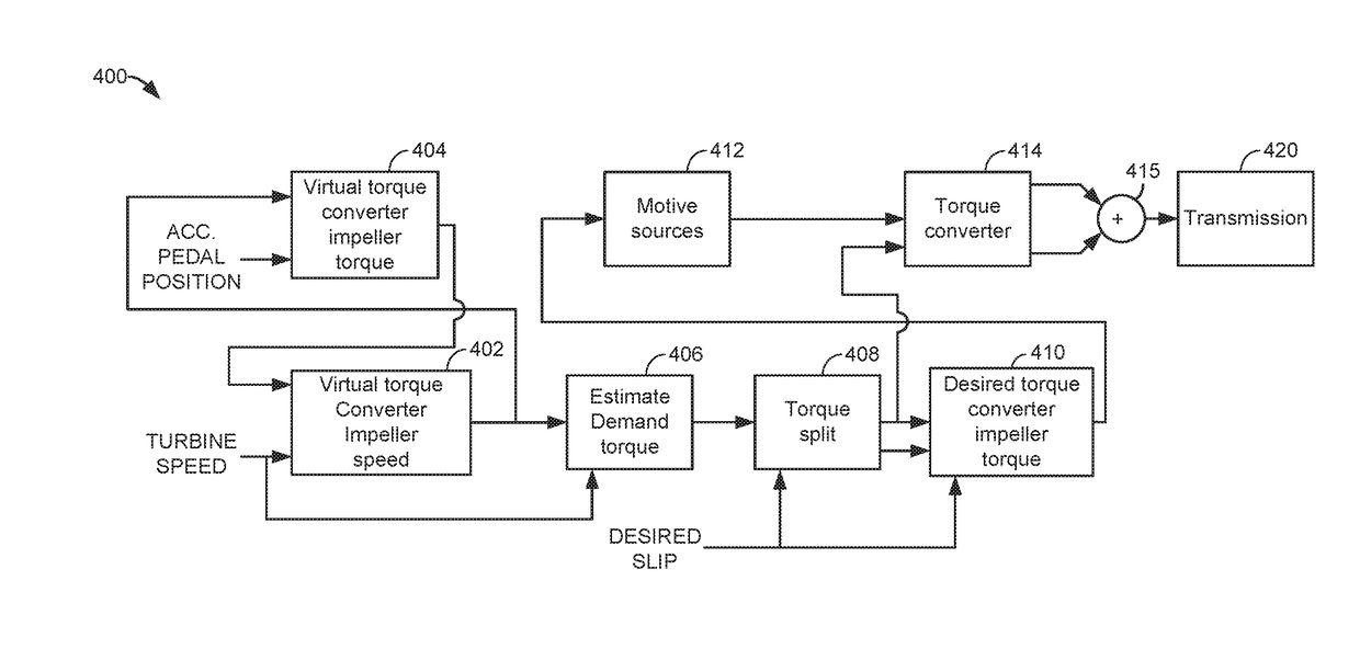
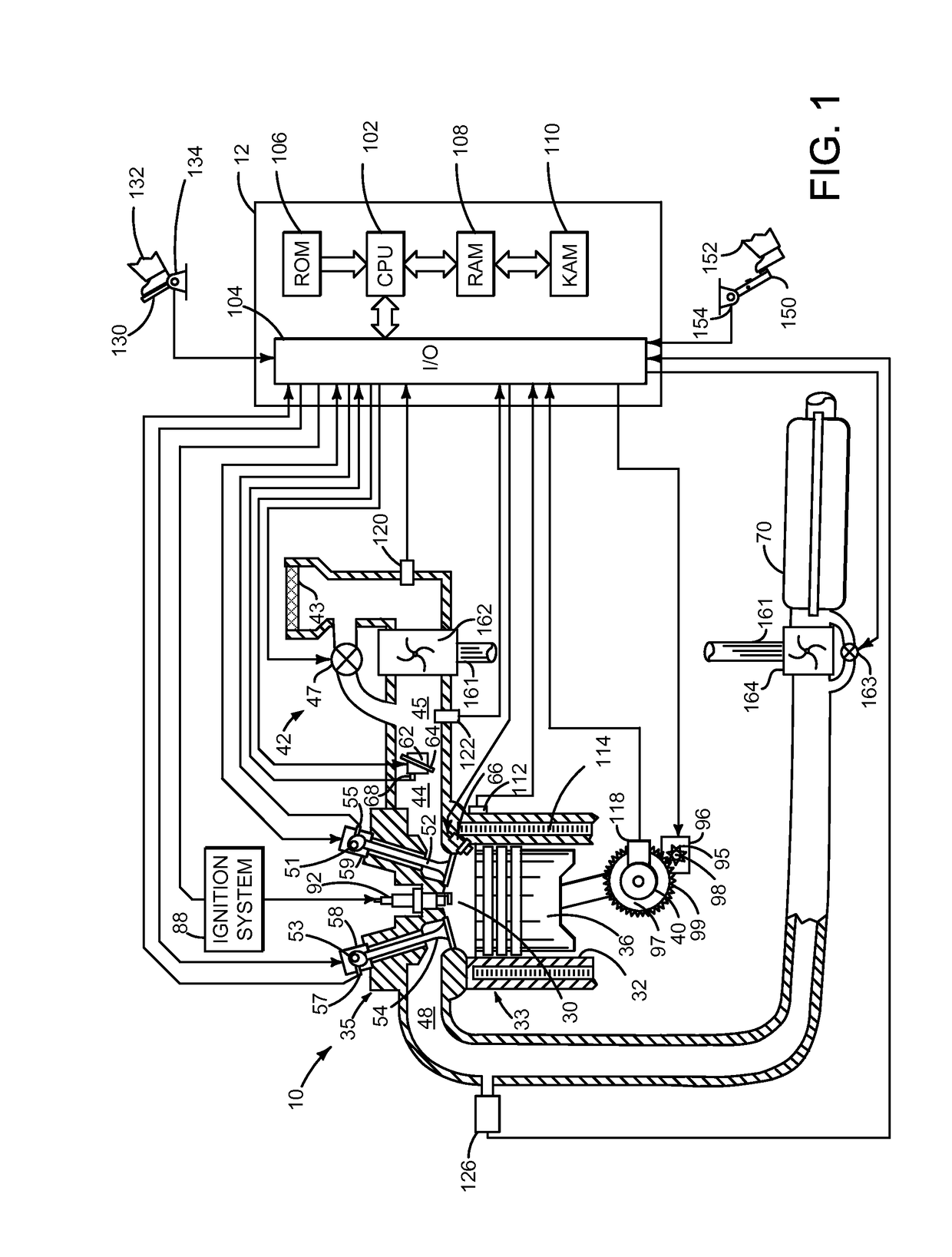
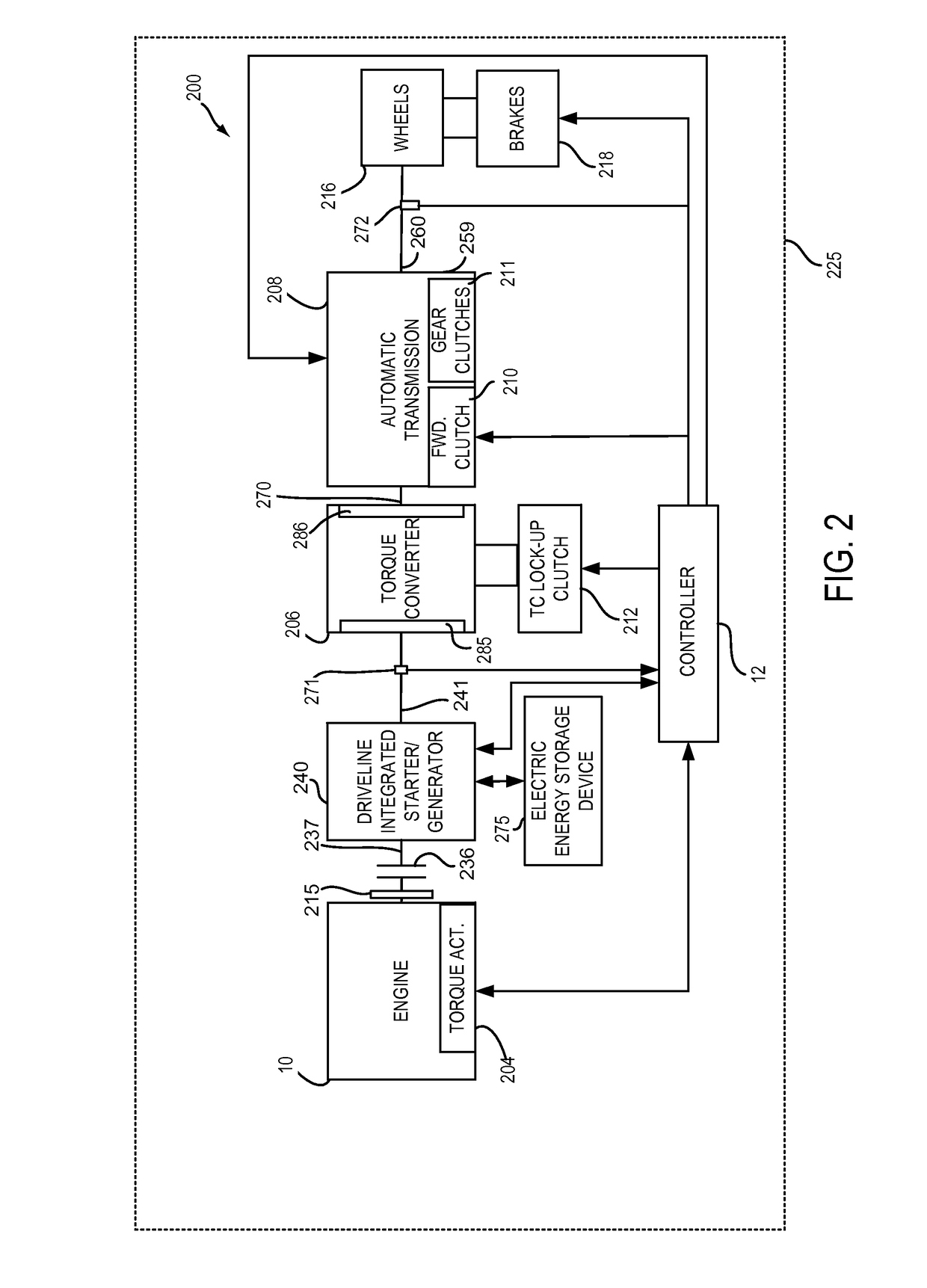
[0014]The present description is related to controlling a driveline of a hybrid vehicle that includes a torque converter and torque converter lockup clutch. The hybrid vehicle may include an engine as is shown in FIG. 1. The engine of FIG. 1 may be included in a powertrain or driveline as is shown in FIG. 2. The driveline may have a torque converter having efficiency as shown in FIG. 3. The hybrid vehicle may be operated according to the method shown in FIGS. 4-11. The hybrid vehicle may launch from stopped or creep (e.g., a condition after vehicle stop where a brake is released and no driver demand has been input where the vehicle may move) conditions as shown in the sequences of FIGS. 12-15.

[0015]Referring to FIG. 1, internal combustion engine 10, comprising a plurality of cylinders, one cylinder of which is shown in FIG. 1, is controlled by electronic engine controller 12. Engine 10 is comprised of cylinder head 35 and block 33, which include combustion chamber 30 and cylinder wa...


PUM


Abstract

Systems and methods for operating a hybrid vehicle driveline that includes an engine and a motor are presented. In one example, the systems and methods include one or more control modes where engine and / or motor speed or torque is adjusted responsive to different control parameters during a vehicle launch from zero speed or a creep speed.

Description

FIELD[0001]The present description relates to methods and a system for controlling a vehicle during launch from a stop or creep. The methods and systems may be particularly useful for hybrid vehicles that include a motor and a torque converter having a lockup clutch.BACKGROUND AND SUMMARY[0002]A driveline of a vehicle may include a torque converter that provides torque multiplication and driveline dampening. The torque multiplication can improve vehicle acceleration from zero speed, but the torque multiplication is a result of operating an engine or motor at a higher speed to create slip across the torque converter. The engine, motor, and torque converter may operate less efficiently when there is a large amount of slip across the torque converter (e.g., a large speed differential between a torque converter impeller and torque converter turbine). Consequently, powertrain efficiency may be reduced more than is desired during vehicle launch. Nevertheless, it may be desirable for the t...

Claims


Application Information

Patent Timeline
Patent Type & Authority Patents(United States)
IPC IPC(8): B60W10/10B60W20/19B60W30/18B60W20/00B60W10/08B60W10/06B60K6/48
CPCB60W10/10B60K6/48B60W10/06B60W10/08B60W20/00B60W20/19B60W30/18027Y10S903/93B60K2006/4825B60W2540/12B60W2710/028Y02T10/6221Y02T10/6252Y02T10/6286B60W10/023B60W30/182B60W2540/10B60W2710/083B60W2710/0666B60W2710/105Y02T10/62
Inventor ZHANG, CHENJOHRI, RAJITKUANG, MING LANGDOERING, JEFFREY ALLENWANG, XIAOYONGORTMANN, WALTER JOSEPHNEDOREZOV, FELIXGIBSON, ALEXANDER O'CONNOR
Owner FORD GLOBAL TECH LLC
Why Eureka
Try Eureka