
Apparatus for the transport and storage of proppant

a proppant and apparatus technology, applied in the oil and gas industry, can solve the problems of difficulty in effective transportation of proppant at the fracturing site, difficulty in effectively transporting, and exposure of proppant to adverse weather conditions, and achieve the effect of improving the transportation and storage of proppan

Active Publication Date: 2017-11-07
SANDBOX ENTERPRISES LLC
View PDF580 Cites 27 Cited by
  • Summary
  • Abstract
  • Description
  • Claims
  • Application Information

AI Technical Summary

Benefits of technology

The patent text recognizes a need to quickly and inexpensively off-load proppant from rail cars in order to improve the velocity, turn-around, and revenue-generating capacity of the rail-car fleet. The hydraulic fracturing method has led to a logistical challenge in delivering the massive quantities of proppant from domestic sand mines to the wellhead, which affects every stakeholder up-and-down the loggression chain.

Problems solved by technology

Applicant has recognized a number of problems in the prior art.
For example, Applicant has recognized that, in any hydraulic fracturing operation, a large amount of proppant is required, and it can be difficult to effectively store the proppant at the fracturing sites.
Additionally, Applicant has recognized the difficulty in effectively transporting the proppant to the desired location.
Under such circumstances, the proppant is exposed to adverse weather conditions.
This may degrade the quality of the proppant during its storage.
Additionally, the maintenance of proppant in containers at the hydraulic fracturing site requires a large capital investment in storage facilities.
With the development and acceptance of the well stimulation methodology known as “hydraulic fracturing,” a unique logistics challenge has been created in delivering the massive quantities of proppant from domestic sand mines to the wellhead.
This logistics challenge affects every stakeholder up-and-down the logistics chain.
Applicant further has recognized that limited storage at trans-loading facilities has severely limited many of the current facilities' ability to operate efficiently.
This requires an intense coordination effort on the part of the trans-loader as well as the trucking community.
Additionally, Applicant has recognized that trans-load terminal locations are not able to move from one area of the shale pay to another, and a potential loss of the investment in such immobile silos can often scare investment capital away from these types of future projects so as to further exacerbate the logistics chain problem.

Method used


Image

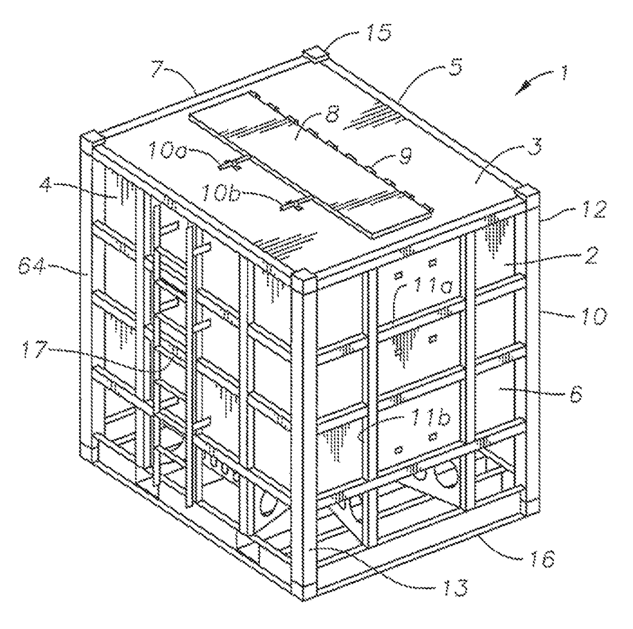
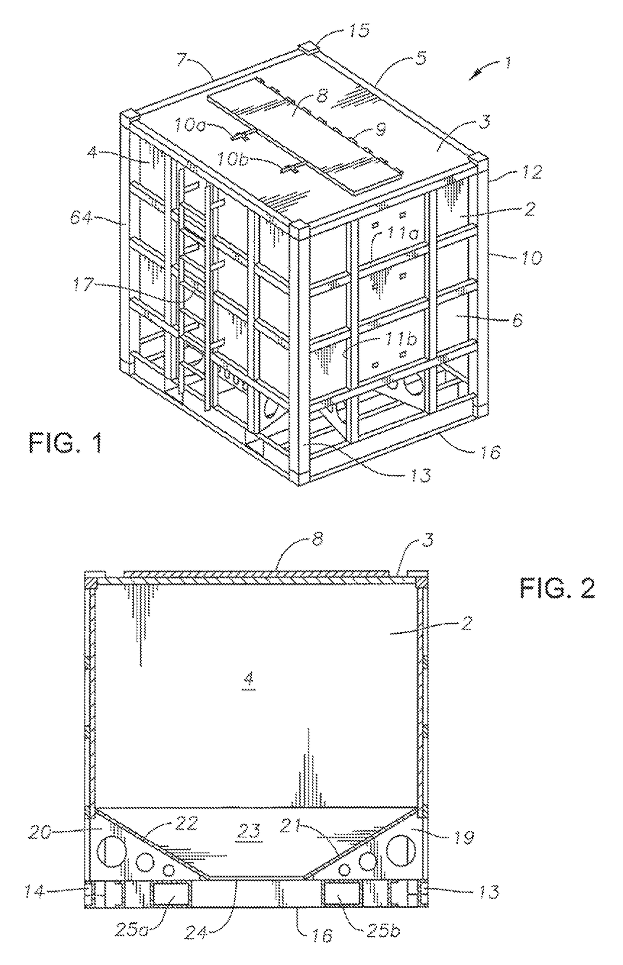
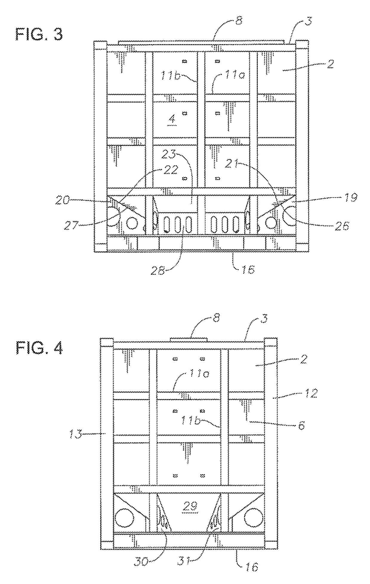
  • Apparatus for the transport and storage of proppant
  • Apparatus for the transport and storage of proppant
  • Apparatus for the transport and storage of proppant

Examples


example 1

[0082]Experiments were conducted with a container in which the side plates had an angle of 30° and the end plates had an angle of 37°. The container had a tare weight of 5,560 pounds. The container was filled with proppant such that the gross weight of the container and the proppant was 43,460 pounds. As such, the total capacity of such container was 37,900 pounds. If the sand was “hand-packed”, then the total capacity of sand is 43,900 pounds. The container had an internal cubic capacity of 512 cubic feet.

[0083]During experiments, it was found that this orientation of side plates and end plates effectively discharged approximately all of the proppant from the container. Generally, however, the container was capable of transporting only 37,900 pounds of sand. As such, the capacity of the container was substantially less than optimal. Because the maximum amount of proppant is desired for every container, it was found that this configuration and orientation of side plates and end plat...

example 2

[0084]The container was modified so that the side plates extended at a 20° angle to horizontal and the end plates extended at 25° angle of the horizontal. The total weight of such container was 5,420 pounds. The internal cubic capacity of such container was 554 cubic feet. As such, only an insufficient amount of proppant could be received in such a container. During experiments with such a configuration, it was found that 4,120 pounds of proppant remained within the container. As such, this orientation of side plates and end plates was found to be ineffective in discharging all of the contents from the container. As a result, less than desired amount of proppant was available for use.

example 3

[0085]Another test was carried out on a container in which the side plates were oriented at a 20° angle with respect to horizontal and the end plates were at a 25° angle with respect to horizontal. The total weight of the container was 5,380 pounds. The gross weight of the container and the sand therein was 46,900 pounds. The container had the capacity of 41,520 pounds. The internal cubic capacity of such a container was 554 feet. It was found that this orientation of such side plates and end plates resulted in less than necessary amount of proppant being contained.


PUM


Abstract

An apparatus for the transport and storage of proppant has a container with a top wall, a pair of end walls and a pair of side walls. The pair of side walls extend between the pair of end walls. The container has a bottom discharge opening. The container includes a funnel extending from the pair of side walls and from the pair of and walls toward the bottom discharge opening. The funnel has sides extending in an angle of greater than 25° with respect to horizontal. The funnel includes a pair of side plates extending respectively from the pair of side walls toward the bottom discharge opening and a pair of end plates extending respectively from the pair of end walls toward the bottom discharge opening. Each of the side plates and the end plates is formed of a stainless steel material.

Description

CROSS-REFERENCE TO RELATED APPLICATIONS[0001]The present invention is a continuation-in-part of U.S. application Ser. No. 13 / 768,962, filed on Feb. 15, 2013, and entitled “Support Apparatus for Moving Proppant from a Container in a Proppant Discharge System”, presently pending. U.S. application Ser. No. 13 / 768,962 is a continuation-in-part of U.S. application Ser. No. 13 / 628,702, filed on Sep. 27, 2012, and entitled “Proppant Discharge System and a Container for Use in Such a Proppant Discharge System”, presently pending. U.S. application Ser. No. 13 / 628,702 is a continuation-in-part of U.S. application Ser. No. 13 / 555,635, filed on Jul. 23, 2012, and entitled “Proppant Discharge System Having a Container and the Process for Providing Proppant to a Well Site”, presently pending. This application further claims priority to and the benefit of U.S. Provisional Application 62 / 012,153, filed on Jun. 13, 2014, and entitled “Process and System for Supplying Proppant from a Mine to a Transp...

Claims


Application Information

Patent Timeline
Patent Type & Authority Patents(United States)
IPC IPC(8): B65D88/12B65D90/12B65D88/30B65D90/58B65G15/42B65G63/00
CPCB65D90/12B65D88/30B65D90/587B65G63/008B65D2590/0091B65G15/42
Inventor OREN, JOHNOREN, JOSHUA
Owner SANDBOX ENTERPRISES LLC
Learn More