
Heated windshield wiper system for vehicle

a technology for windshield wipers and vehicles, applied in vehicle maintenance, vehicle cleaning, transportation and packaging, etc., can solve the problems of significant road hazards, poor operation of wiper blades, and build-up of ice on vehicle windshield wiper blades

Active Publication Date: 2017-11-14
THERMALBLADE
View PDF5 Cites 4 Cited by
  • Summary
  • Abstract
  • Description
  • Claims
  • Application Information

AI Technical Summary

Benefits of technology

[0022]Preferably the heating element being arranged for connection by conductors to an electrical supply arranged to supply electrical power to the heating elements and the conductors are contained within a housing of the wiper blade to make it more cosmetically appealing.
[0038]wherein the conductors are contained within a housing of the wiper blade to make it more cosmetically appealing.
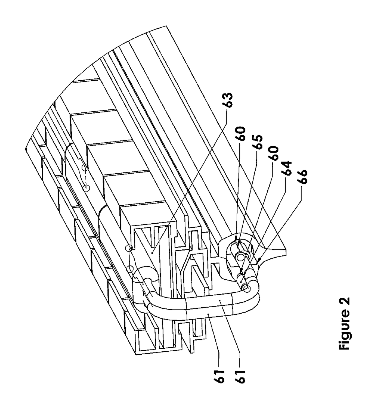
[0074]2 The system uses conductors supplying the power source to the heating element into the housing of the wiper frame to make it more cosmetically appealing. This is accomplished either using a two wire conductor or a PC Board placed in a cavity underneath the housing and or along the length or part length of the frame.
[0080]According to a yet further important aspect of the present invention, the wires connected to the heating element are mounted using special designed plastic or metal clips so as to make the design more cosmetically appealing.

Problems solved by technology

In colder climates, the build-up of ice on vehicle windshield wiper blades is a common problem.
The ice causes the wiper blades to operate poorly which is an annoyance to drivers and can become a significant road hazard if the visibility of the driver through the windshield is significantly reduced.
The periodical replacement of the wipers can thus be expensive and requires time consuming assembly.
In the event that the wiper blade requires replacement however considerable rewiring of the heating element is required.
The heating element and selective coupling in this instance however are required to be formed integrally with the wiper blade and therefore do not permit independent replacement of the various components of the wiper assembly.

Method used


Image

  • Heated windshield wiper system for vehicle
  • Heated windshield wiper system for vehicle
  • Heated windshield wiper system for vehicle

Examples


Embodiment Construction

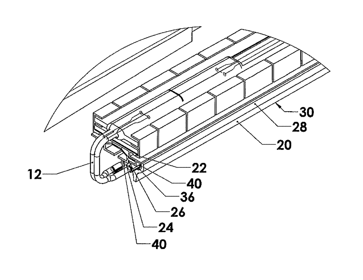
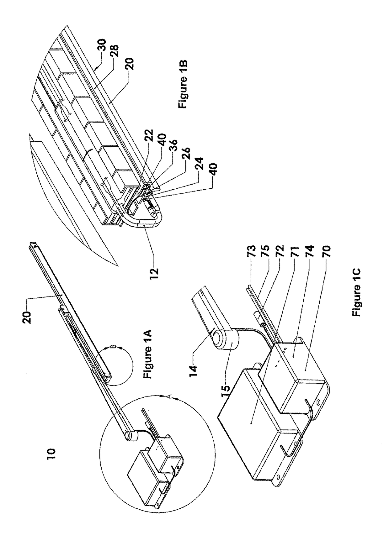
[0088]Referring to the accompanying drawings, in FIGS. 1A, 1B, 1C and 2 there is illustrated a wiper assembly generally indicated by reference numeral 10 having a wiper heating system 12 mounted thereon. The wiper heating system 12 is arranged to heat the wiper blade 20 of the wiper assembly 10 so as to prevent the build-up of ice thereon when in use in colder climates.

[0089]The wiper assembly 10 includes a wiper arm 14 which is pivotally mounted at its base as in a conventional vehicle wiper blade assembly. A tension spring is mounted at the base of the arm so as to bias the arm against the windshield of a vehicle having the assembly mounted thereon. An articulation joint is mounted at a free end of the arm for pivotally and selectively mounting a wiper blade thereon. The wiper blade 20 includes a longitudinally extending wiper receiving channel 22 for mounting a wiper element 24 therein.

[0090]The wiper heating system 12 includes the wiper element 24 in the form of an elongate resi...


PUM


Abstract

A heated wiper system includes a wiper blade with a resilient wiper element having a passage along the wiper element from an opening at one end of where a heating element is inserted into the passage. The temperature of the heating element is controlled by controlling the current supplied to the element by a control unit contained either in the engine compartment or in a recess on the wiper blade. The control unit uses an algorithm including wiper blade and outside ambient temperature, wind chill, ignition on, motor running, heating element resistance value and wipers and varies the current supplied in dependence on a value of the resistance of the heating element.

Description

CROSS-REFERENCE TO RELATED APPLICATIONS[0001]This application claims domestic priority on U.S. Provisional Patent Application Ser. No. 61 / 758,843, filed on Jan. 31, 2013, the content of which is incorporated herein by reference.[0002]This invention relates to a heated windshield wiper system for a vehicle.BACKGROUND OF THE INVENTION[0003]In colder climates, the build-up of ice on vehicle windshield wiper blades is a common problem. The ice causes the wiper blades to operate poorly which is an annoyance to drivers and can become a significant road hazard if the visibility of the driver through the windshield is significantly reduced.[0004]Various wiper heating devices have attempted to overcome the problem of ice build-up on wiper blades by mounting a heating element in close proximity to or directly in engagement with the wiper blades. In order for the heating element to operate effectively it is generally required that the heating element directly engage the wiper blade. Known heat...

Claims


Application Information

Patent Timeline
Patent Type & Authority Patents(United States)
IPC IPC(8): B60S1/38
CPCB60S1/3805B60S1/3848B60S2001/3836B60S2001/3818B60S1/381B60S1/3882B60S1/4006
Inventor KLEINSASSER, GEORGEKLEINSASSER, HARRY
Owner THERMALBLADE
Learn More