Hydrostatic drive system in a closed circuit

a drive system and closed circuit technology, applied in the direction of fluid gearings, gearing control, belts/chains/gearrings, etc., can solve the problems of large space occupation, large design effort and expense, and two individual drive units occupying a large amount of space, so as to achieve simple and economical manner

Inactive Publication Date: 2017-11-14
LINDE HYDRAULICS
View PDF4 Cites 5 Cited by
  • Summary
  • Abstract
  • Description
  • Claims
  • Application Information

AI Technical Summary

Benefits of technology

[0012]The invention accomplishes this object in that the hydrostatic drive unit and the additional hydrostatic drive unit are in the form of a hydrostatic dual-flow double drive unit which is provided with or in the accumulator flow path between one of the two hydraulic connections and the hydrostatic accumulator and which is provided with or in the tank flow path between the other of the two hydraulic connections and the tank. The invention therefore teaches that only a single hydrostatic double drive unit with two separate flow paths and flow streams is provided for the quantity and / or volume balance that is required on account of hybrid function by the hydrostatic accumulator, which has the accumulator flow path as well as the tank flow path and therefore performs the function of the hydrostatic drive unit and the function of the additional hydrostatic drive unit. The dual-flow double drive unit of the invention has two delivery flows that are separated from each other, one delivery flow of which forms the accumulator flow path and the other delivery flow of which forms the tank flow path. A dual-flow double drive unit occupies a small amount of space, so that the quantity and / or volume balance necessary for the hybrid function can be achieved in a compact manner. In addition, a dual-flow double drive unit has a simple and economical construction compared to two separate hydrostatic individual drive units of the prior art. A further advantage of the dual-flow double drive unit is that with the double drive unit, it is possible in a simple manner in a hydrostatic drive with a closed circuit to achieve a theoretically exact balancing of the amount of hydraulic fluid in the low-pressure side hydraulic connection during the extraction or the addition of a quantity of hydraulic fluid to the high-pressure side hydraulic connection, so that the quantity and / or volume balance in the two hydraulic connections of the closed circuit is guaranteed with little extra construction effort or expense.
[0013]In one preferred embodiment, the double drive unit has the same displacement volume for the accumulator flow path and the tank flow path. The double drive unit, which performs the function of the hydrostatic drive unit and the function of the additional hydrostatic drive unit, therefore supplies two equal delivery flows and on account of the same displacement volume in the two flow paths makes possible a theoretically exact balancing of the amount of hydraulic fluid in the low-pressure side hydraulic connection during the extraction or the addition of a quantity of hydraulic fluid at the high-pressure side hydraulic connection.

Problems solved by technology

This design entails a great deal of construction effort and expense and occupies a large amount of space, because each of the two individual drive units has a separate housing and a separate shaft with the corresponding shaft bearing in the respective housing of the corresponding individual drive unit.
The shaft required for the coupling of the two individual drive units or the transmission required for the coupling of the two individual drive units also entails a great deal of construction effort and expense and occupies a large amount of space.
The hybrid function described in DE 10 2009 011 247 A1 with a hydrostatic accumulator and two additional hydrostatic drive units, each of which is in the form of an individual drive unit, therefore occupies a large amount of space, entails a great deal of extra manufacturing effort and expense, and makes the entire system more complex and expensive.

Method used


Image

  • Hydrostatic drive system in a closed circuit
  • Hydrostatic drive system in a closed circuit
  • Hydrostatic drive system in a closed circuit

Examples


Embodiment Construction

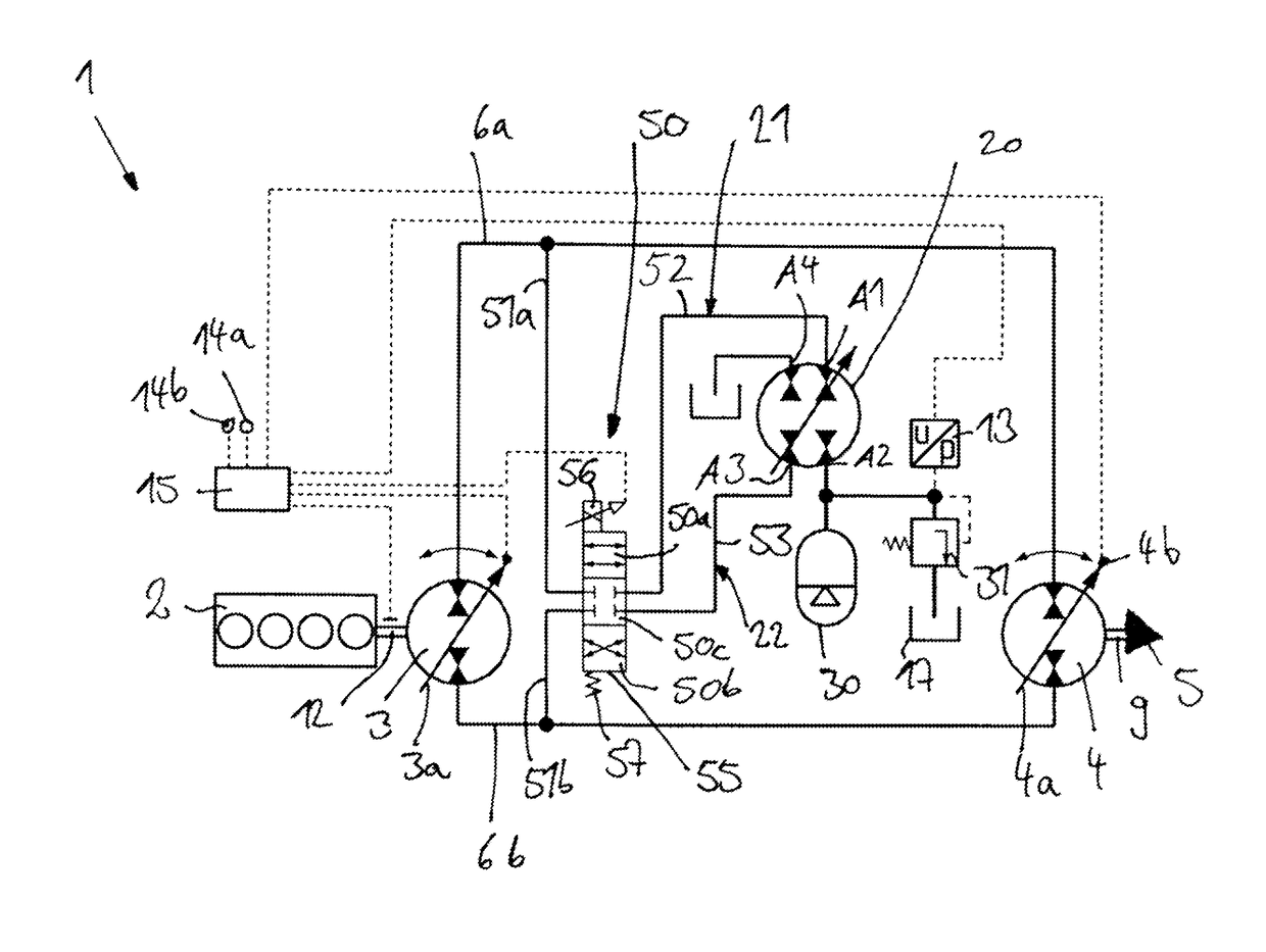
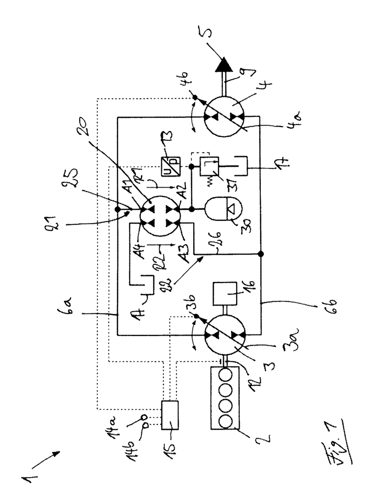
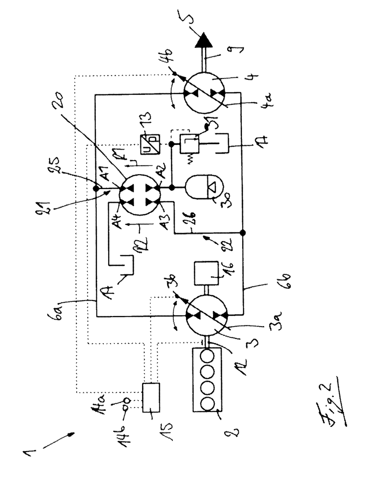
[0067]FIGS. 1 and 2 show a drive train of a vehicle with a hydrostatic drive system 1 of the invention.

[0068]The hydrostatic drive 1 has a hydrostatic pump 3 which is driven by a drive motor 2 and is connected in a closed circuit with a hydrostatic motor 4. The motor 4 is in a drive connection with a consumer 5. The closed circuit is formed by a first hydraulic connection 6a and a second hydraulic connection 6b.

[0069]In the illustrated exemplary embodiment the drive motor 4 is an internal combustion engine.

[0070]In the illustrated exemplary embodiment (e.g. FIG. 3), the consumer 5 is a traction drive system of a vehicle and comprises a drive axle 7 with two driven wheels 8a, 8b. An output shaft 9 of the motor 4 is in communication with a differential transmission 10 of the drive axle 7, which drives the wheels 8a, 8b by means of corresponding output shafts. The drive axle 7 can be driven directly by the motor 4. In the illustrated exemplary embodiment, the motor 4 is in a drive con...


PUM


Abstract

A hydrostatic drive system (1) has a hydrostatic pump (3) driven by a drive motor (2) and connected in a closed circuit with a hydrostatic motor (4). The hydrostatic motor (4) drives a consumer (5) and the closed circuit is formed by a first hydraulic connection (6a) and a second hydraulic connection (6b). A hydrostatic accumulator (30) can be connected with at least one of the two hydraulic connections (6a, 6b). A hydrostatic drive unit is located in an accumulator flow path (21) between one of the two hydraulic connections (6a, 6b) and the hydrostatic accumulator (30) and an additional hydrostatic drive unit is located in a tank flow path (22) between the other of the two hydraulic connections (6a, 6b) and a tank (17). The hydrostatic drive unit and the additional hydrostatic drive unit are a hydrostatic dual-flow double drive unit (20) provided in the accumulator flow path (21) and in the tank flow path (22).

Description

CROSS REFERENCE TO RELATED APPLICATIONS[0001]This application claims priority to German Application No. DE 102013114038.6 filed Dec. 13, 2013, which is herein incorporated by reference in its entirety.BACKGROUND OF THE INVENTION[0002]Field of the Invention[0003]This invention relates to a hydrostatic drive system with a hydrostatic pump which is driven by a drive motor and is connected in a closed circuit with a hydrostatic motor. The hydrostatic motor is in a drive connection with a consumer. The closed circuit is formed by a first hydraulic connection and a second hydraulic connection. A hydrostatic accumulator device can be connected with at least one of the two hydraulic connections for the storage of energy and the discharge of energy. A hydrostatic drive unit is located in an accumulator flow path between one of the two hydraulic connections and the hydrostatic accumulator and an additional hydrostatic drive unit is located in a tank flow path between the other of the two hydr...

Claims


Application Information

Patent Timeline
Patent Type & Authority Patents(United States)
IPC IPC(8): F16H61/4096B60K6/12F16H39/10F15B1/02F15B1/027F15B15/18F16H61/44F16H61/42F16H61/4139
CPCF15B1/027B60K6/12F15B1/024F15B15/18F16H39/10F16H61/42F16H61/44F16H61/4096F16H61/4139F15B2201/411F15B2211/214B60K2006/126Y02T10/62
Inventor KRITTIAN, LUKAS
Owner LINDE HYDRAULICS
Why Eureka
Try Eureka