
Deformable latch mechanism for tray

a latch mechanism and tray technology, applied in the direction of instruments, fibre mechanical structures, optical light guides, etc., can solve the problem of only accessible mechanisms

Active Publication Date: 2017-12-12
BELDEN CANADA ULC
View PDF2 Cites 9 Cited by
  • Summary
  • Abstract
  • Description
  • Claims
  • Application Information

AI Technical Summary

Benefits of technology

The invention is an optic fiber equipment housing with a tray and a latch mechanism for securely positioning the tray in two different positions. The latch mechanism consists of two notches on the housing and an elongate actuator on the tray, which can engage with the notches to secure the tray in one of two positions. The actuator has two elongate members and a stop that can be moved from an unactuated state to an actuated state to secure the tray in either position. This design allows for easy and secure positioning of the optic fiber equipment.

Problems solved by technology

One drawback is that these mechanisms are only accessible from the front of the tray.

Method used


Image

  • Deformable latch mechanism for tray
  • Deformable latch mechanism for tray
  • Deformable latch mechanism for tray

Examples


Embodiment Construction

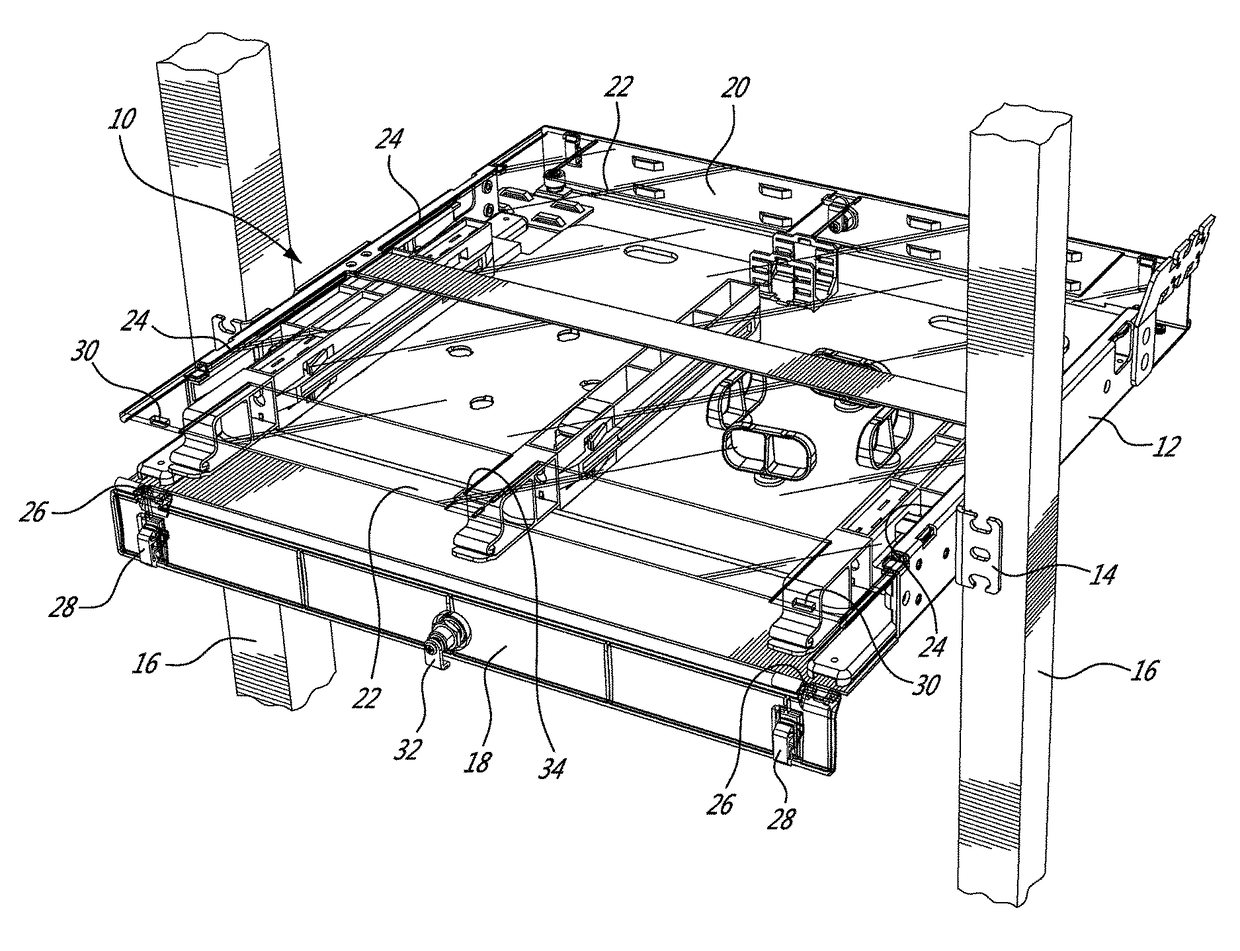
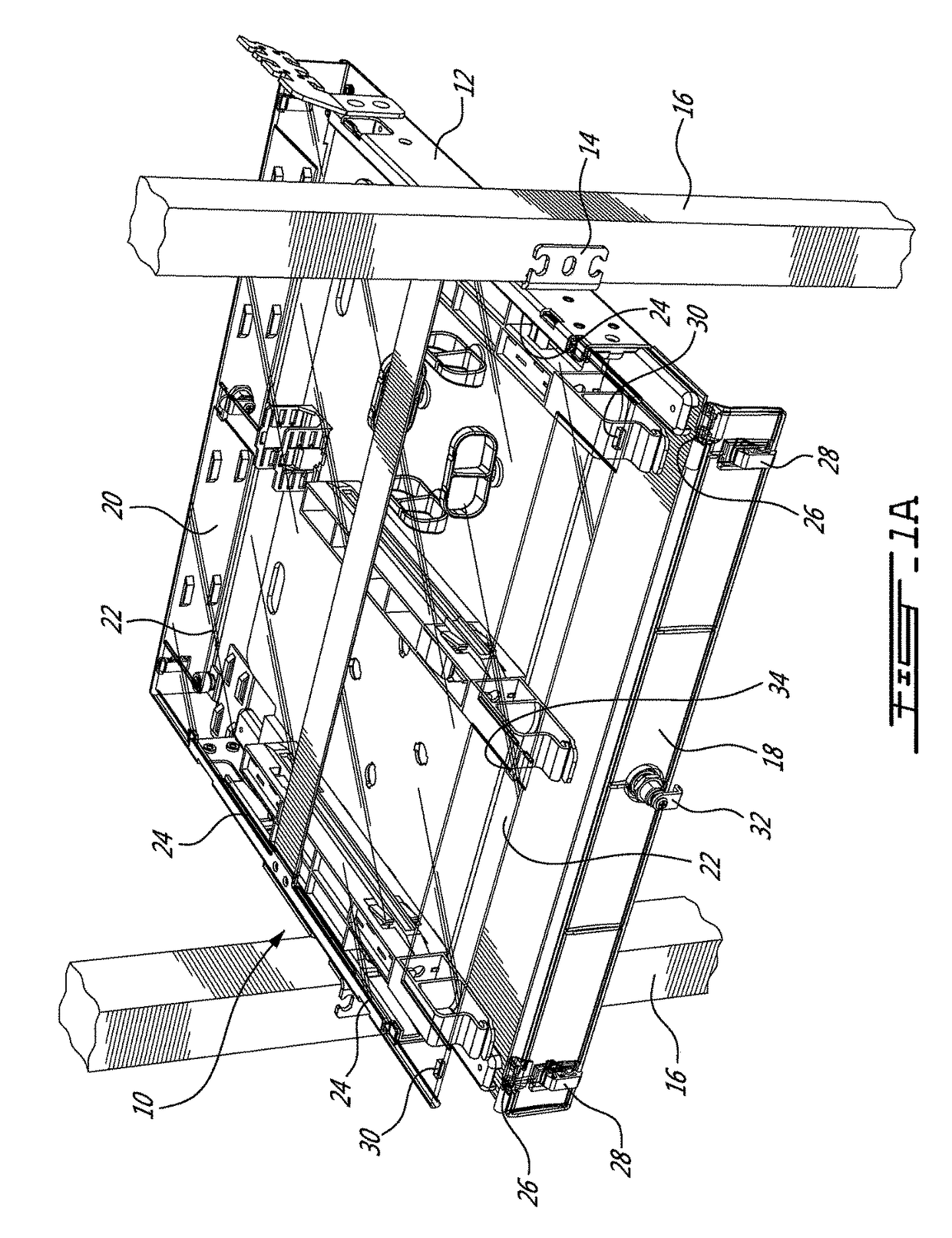
[0010]Referring now to FIG. 1A, a fiber optic equipment, generally referred to using the reference numeral 10, will now be described. The fiber optic equipment 10 comprises a housing 12 illustratively attachable by way of brackets 14 to a 19″ (19 inch) rack 16. The housing 12 defines openings which may be closed by doors 18, 20. In particular embodiment the edges of the tops 22 are retained in opposed grooves 24 in the housing 12 and are removable by sliding the tops 22 out of the grooves 24. Additionally, the tops 22 may be manufactured from a transparent material such as polycarbonate or the like and such that a user may more readily view inside the housing 12. The doors 18, 20 are attached to the housing via hinges 26 and such that they may be moved between an open position and a closed position. Door catches 28 are provided on either end of the door which engage complementary cut outs 30 in the tops 22 to retain the doors 18, 20 in the closed position. Additionally, a key actuat...


PUM


Abstract

A latch mechanism for retaining a tray in a selected one of a first, second position and third position. The latch mechanism comprises notches arranged on an inner surface of the housing along an axis parallel to a direction of travel of the tray, an elongate actuator on the tray and opposite the inner surface, the actuator comprising a first elongate member and a second elongate member, an inner end of the first elongate member connected to an inner end of the second elongate member at a connection point, a stop positioned at the connection point wherein the stop is biased laterally towards the inner surface. By increasing a distance between an outer end of the first elongate member and an outer end of the second elongate member the stop is moveable from an unactuated state wherein the stop is engageable by a selected one of the notches and such that the tray is retainable in a selected one of the first, second and third position, to an actuated state wherein the stop moves laterally against the biasing force away from the inner surface and such that the stop is no longer engageable by one of the notches.

Description

[0001]This application claims benefit under 35 U.S.C. §119(e) of U.S. provisional application Ser. No. 62 / 347,162 filed on Jun. 8, 2016 which is incorporated herein in its entirety by reference.FIELD OF THE INVENTION[0002]The present invention relates to a deformable latch mechanism for tray.BACKGROUND TO THE INVENTION[0003]The prior art discloses sliding trays including a latch mechanism which can be engaged and disengaged to selectively allow the tray to be held or to slide. One drawback is that these mechanisms are only accessible from the front of the tray. As such, there is a need for a latch mechanism which can be actuated equally from both the front and the back of the tray.SUMMARY OF THE INVENTION[0004]In order to address the above and other drawbacks there is provided an optic fiber equipment comprising an equipment housing configured for mounting in a 19″ rack, the housing defining a front opening and a rear opening opposite the front opening, a tray disposed within the ho...

Claims


Application Information

Patent Timeline
Patent Type & Authority Patents(United States)
IPC IPC(8): G02B6/00G02B6/44G02B6/38
CPCG02B6/4452G02B6/4453G02B6/3897G02B6/44526
Inventor PILON, VINCENT
Owner BELDEN CANADA ULC
Learn More