Oscillating positive respiratory pressure device

a positive, oscillating technology, applied in the direction of respirators, medical devices, other medical devices, etc., can solve the problems of reducing the effectiveness of bronchial obstruction, and splitting open obstructed airways, so as to achieve rapid increase of pressure in the mouthpiece 112 and increase of pressure in the mouthpiece 112

Active Publication Date: 2017-12-26
TRUDELL MEDICAL INT INC
View PDF175 Cites 13 Cited by
  • Summary
  • Abstract
  • Description
  • Claims
  • Application Information

AI Technical Summary

Problems solved by technology

However, for individuals suffering from more significant bronchial obstructions, such as collapsed airways, a single cough may be insufficient to clear the obstructions.
It is believed that OPEP therapy, or the oscillation of exhalation pressure at the mouth during exhalation, effectively transmits an oscillating back pressure to the lungs, thereby splitting open obstructed airways and loosening the secretions contributing to bronchial obstructions.

Method used


Image

  • Oscillating positive respiratory pressure device
  • Oscillating positive respiratory pressure device
  • Oscillating positive respiratory pressure device

Examples


first embodiment

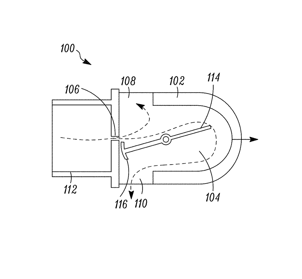
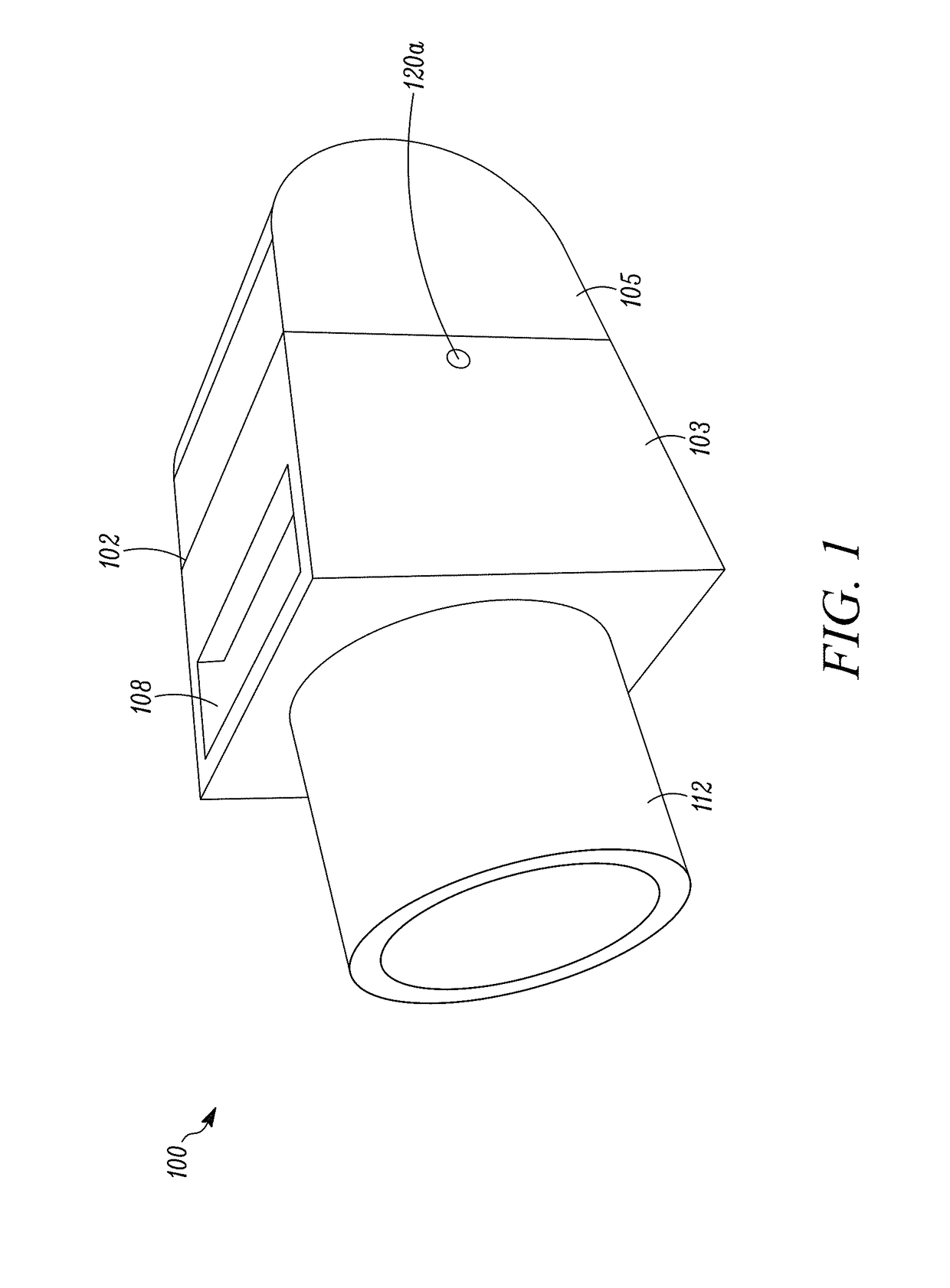
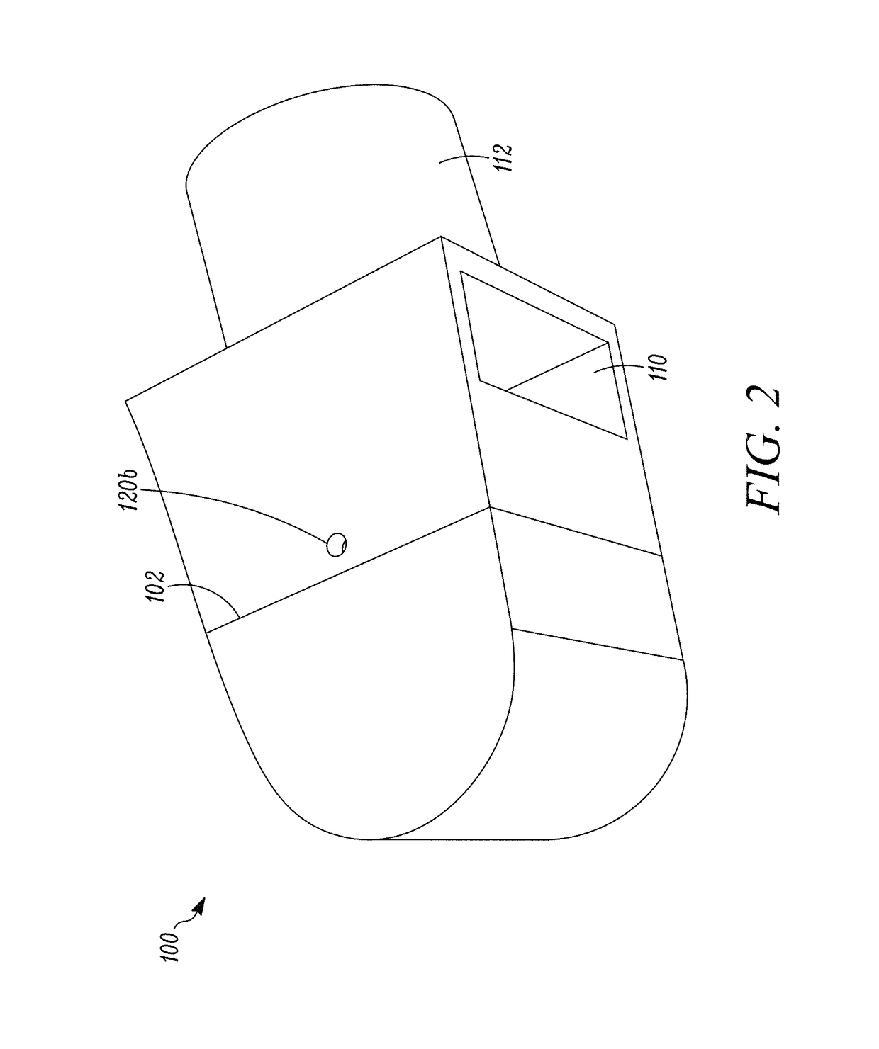
[0038]Referring to FIGS. 1-4, an OPEP device100 is shown. In general, the OPEP device 100 includes a housing 102 enclosing a chamber 104, a chamber inlet 106, a first chamber outlet 108, a second chamber outlet 110, a mouthpiece 112 in communication with the chamber inlet 106, a vane 114 mounted within the chamber 104, and a blocking member 116 disposed on the vane 114.

[0039]The housing 102 and OPEP device 100 components may be constructed of any durable material, such as a low friction plastic or polymer, and may include a front section 103 and a rear section 105 that are removably attachable such that the chamber 104 may be periodically accessed for cleaning and / or replacement of the vane 114. In addition, although the mouthpiece 112 is shown as being fixedly attached to the housing 102, it is envisioned that the mouthpiece 112 may be removeable and replaceable with a mouthpiece of a different shape or size. Preferably, the size or cross-sectional area of the mouthpiece 112 is gre...

second embodiment

[0050]Referring to FIGS. 7-13, an OPEP device 200 is shown. In general, the OPEP device 200 includes a housing 202 enclosing a chamber 204 having a first portion 207 and a second portion 209 joined by a passage 211, a chamber inlet 206, a chamber outlet 208, a mouthpiece 212 in communication with the chamber inlet 206, a turbine 214 rotatably mounted within the chamber 204 via a shaft 218, a blocking member 216, a first linkage 220, and a second linkage 222.

[0051]The housing 202 and OPEP device 200 components may be constructed of any durable material, such as a low friction plastic or polymer, and may include a front cover 203 and a rear cover 205 that are removably attachable such that the chamber 204 may be periodically accessed for cleaning and / or replacement of the turbine 214 and / or linkages 220, 222. In addition, although the mouthpiece 212 is shown as being fixedly attached to the housing 202, it is envisioned that the mouthpiece 212 may be removeable and replaceable with a ...

third embodiment

[0056]Turning to FIGS. 14-19, an OPEP device 300 is shown. In general, the OPEP device 300 includes a housing 302 enclosing a chamber 304, a chamber inlet 306, a chamber outlet 308, a vent 338, a mouthpiece 312 in communication with the chamber inlet 306, a turbine 314 rotatably mounted within the chamber 304 via a shaft 318, a blocking member 316, and a pair of arms 320, 322 operatively connected to the shaft 318.

[0057]The housing 302 and OPEP device 300 components may be constructed of any durable material, such as a low friction plastic or polymer, and may include an upper section 303, an inner section 301, and a lower section 305 that are removably attachable such that the chamber 304 may be periodically accessed for cleaning and / or replacement of the turbine 314. In addition, although the mouthpiece 312 is shown as being fixedly attached to the housing 302, it is envisioned that the mouthpiece 312 may be removeable and replaceable with a mouthpiece of a different shape or size....


PUM


Abstract

A respiratory treatment device includes a housing enclosing a chamber, a chamber inlet configured to receive a flow of air into the chamber, a first chamber outlet configured to permit the flow of air to exit the chamber, and a second chamber outlet configured to permit the flow of air to exit the chamber. A vane mounted within the chamber is configured to rotate between a first position where the flow of air is directed to exit the chamber through the first chamber outlet, and a second position where the flow of air is directed to exit the chamber through the second chamber outlet. A blocking member disposed on the vane is moveable relative to the chamber inlet between a closed position where the flow of air through the chamber inlet is restricted, and an open position where the flow of air through the chamber inlet is less restricted.

Description

RELATED APPLICATION[0001]This application claims the benefit of U.S. Provisional Application No. 61 / 868,667, filed on Aug. 22, 2013, pending, which is incorporated herein by reference.TECHNICAL FIELD[0002]The present disclosure relates to a respiratory treatment device, and in particular, to an oscillating positive respiratory pressure device.BACKGROUND[0003]Each day, humans may produce upwards of 30 milliliters of sputum, which is a type of bronchial secretion. Normally, an effective cough is sufficient to loosen secretions and clear them from the body's airways. However, for individuals suffering from more significant bronchial obstructions, such as collapsed airways, a single cough may be insufficient to clear the obstructions.[0004]One type of therapy, utilizing oscillating positive expiratory pressure (“OPEP”), is often used to address this issue. OPEP therapy represents an effective bronchial hygiene technique for the removal of bronchial secretions in the human body and is an...

Claims


Application Information

Patent Timeline
Patent Type & Authority Patents(United States)
IPC IPC(8): A61M16/00A61M16/20
CPCA61M16/0006A61M16/208A61M2210/0625
Inventor MEYER, ADAMENGELBRETH, DAN
Owner TRUDELL MEDICAL INT INC
Why Eureka
Try Eureka