Tank

a tank and cap technology, applied in the field of tanks, can solve the problems of small force by which the cap which has been elastically deformed returns to its original shape, and the cap installed in the inlet port might be inadvertently or unintentionally detached or come off from the inlet port, and achieve the effect of suppressing any liquid scattering

Active Publication Date: 2018-01-16
BROTHER KOGYO KK
View PDF7 Cites 0 Cited by
  • Summary
  • Abstract
  • Description
  • Claims
  • Application Information

AI Technical Summary

Benefits of technology

[0009]The present teaching has been made in view of the above-described situations, and an object of the present teaching is to provide a tank capable of achieving at least one of the followings: capability of easily attaching / detaching the cap with respect to the inlet port of the tank; capability of suppressing any scattering of a liquid such as an ink when the cap is removed from the inlet port; and capability of suppressing any inadvertent detaching of the cap from the inlet port.
[0019]According to the above-described configuration, the cap is provided with the seal portion and the plurality of stoppers separately from each other. The seal portion has the function of sealing the inlet port in the liquid-tight manner. The plurality of stoppers have the function of suppressing any detachment of the cap from the inlet port. Even in a case of elastically deforming the cap so as to install the cap in the inlet port in order that the cap is moved up to a position at which the abutting surface of each of the plurality of stoppers can contact the tank toward the first direction, the plurality of stoppers are provided on the cap while being spaced from each other in the circumferential direction of the cap. Accordingly, the cap is elastically deformed with a force smaller than a force in a case that the stoppers are provided on the cap along the entire circumference thereof in the circumferential direction. Thus, a user can install the cap in the inlet port by moving the cap, with a relatively small force, up to the position at which the abutting surface of each of the stoppers can contact the tank in the first direction. Similarly, also in a case of removing the cap from the inlet port by elastically deforming the cap so as to release the contact of the abutting surface with respect to the tank, the plurality of stoppers are provided on the cap while being spaced from each other in the circumferential direction of the cap. Accordingly, the cap is elastically deformed with a force smaller than the force in the case that the stoppers are provided on the cap along the entire circumference thereof in the circumferential direction. Thus, the user can remove the cap from the inlet port by releasing the contact of the abutting surface of each of the stoppers with respect to the tank, with a relatively small force. Further, the plurality of stoppers are provided on the cap while being spaced from each other in the circumferential direction of the cap. Accordingly, by for example rotating the cap about the first direction, the cap can be moved up to the position at which the abutting surface of each of the stoppers can contact with respect to the tank in the first direction, without elastically deforming the cap, thereby making it possible to attach the cap to the inlet port. Similarly, by for example rotating the cap about the first direction, the contact of the abutting surfaces of the respective stoppers with respect to the tank can be released so as to detach the cap from the inlet port, without elastically deforming the cap.
[0020]Furthermore, when the cap is being detached from the inlet port, the force by which the cap which has been elastically deformed returns to its original shape is small. Thus, even if any liquid such as an ink is adhered to the cap, it is possible to suppress any scattering of the ink adhered to the cap.
[0021]Moreover, since the seal portion and the stoppers are provided independently from each other, the sealing function of the seal portion is not lowered even though the stoppers are not provided along the entire circumference in the circumferential direction of the cap.
[0022]Further, in a case that the cap is being moved toward the first direction from the state of being installed in the inlet port, the abutting surface of each of the stoppers contacts the tank, and forces mutually pressing in opposite directions act on the space between the abutting surface of each of the stoppers and the tank. Thus, in a case that the inner pressure in the tank becomes greater than the atmospheric pressure, or in another case that the tank is turned upside down in the up-down direction and the weight of the ink inside the tank is applied to the cap, there is little fear that the cap installed in the inlet port might be detached or come off from the inlet port.
[0024]Further, according to the present teaching, when the cap is removed from the inlet port, the cap which has been elastically deformed returns to its original shape with a relatively weak force, it is possible to suppress any scattering of the liquid such as the ink adhered to the cap.

Problems solved by technology

On the other hand, however, under a condition that the frictional force is small, there is such a fear that, when for example the inner pressure in the tank becomes greater than the atmospheric pressure, or when the ink-jet printer is turned upside down in the up-down direction and the weight of the ink inside the tank is applied to the cap, the cap installed in the inlet port might be inadvertently or unintentionally detached or come off from the inlet port.
Further, there is also such a fear that, when the cap is removed from the inlet port, the umbrella portion which has been elastically deformed inside the inlet port is pulled out from the inlet port and restored to the original shape of the umbrella portion, and thereby might allow any ink adhered to the umbrella portion to scatter.
Furthermore, when the cap is being detached from the inlet port, the force by which the cap which has been elastically deformed returns to its original shape is small.

Method used


Image

  • Tank
  • Tank
  • Tank

Examples


second embodiment

[0155]In the above-described second embodiment, the engaging portions 202 may be provided with stopper portions, respectively, in order to stop the rotation of the cap 191 at a position at which each of the engaging portions 202 and one of the stoppers 197 do not face each other in the first direction 155. For example, the stopper portions are provided so as to project, in the first direction 155 and in the direction opposite to the first direction 155, from the side end edge portions 202B in a first rotational direction 230 in the circumferential direction of the respective engaging portions 202. The stopper portions each have a plane parallel to the central axis line 151.

[0156]In a case of attaching the cap 191 to the inlet port 192, the user presses the cap 191 toward the inlet port 192 until the stoppers 197 abut against the engaging portions 202, respectively, and then the user rotates the cap 191 in a direction opposite to the first rotational direction 230 about the central a...

third embodiment

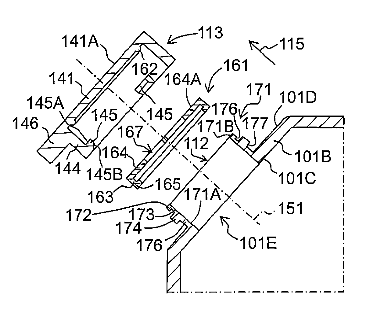
[0166]The shape of the outer circumferential surface of the cylindrical wall 121 of the inlet port 112 in the third embodiment is not particularly limited, and the outer circumferential surface of the cylindrical wall 121 may have any shape.

[0167]In a case of attaching the cap 210 to the inlet port 112, the user presses the cap 210 toward the inlet port 112 such that the insertion portion 212 is inserted inside the inlet port 112. In this situation, the inner guide surface 121C of the cylindrical wall 121 abuts against (contacts) the guide surface 214B of each of the stoppers 214 while a force moving the cap 210 in the direction opposite to the first direction 155 is applied to the cap 210. With this, the stoppers 214 are elastically deformed to be compressed to the inside of the radial directions of the cylindrical wall 121 and the inlet port 112, and the insertion portion 212 and the seal portion 213 are elastically deformed such that the diameters of the insertion portion 212 and...


PUM


Abstract

There is provided a tank including: a liquid storage chamber; an outer wall having an inner surface and an outer surface; a cylindrical wall; an inlet port; an outlet port; and a cap for the inlet port. The cap has a seal portion configured to contact an inner circumferential surface of the cylindrical wall or of the outer wall defining the inlet port, or contact an end surface of the cylindrical wall exposed to the outside of the tank, in a state that the cap is installed in the inlet port; and a plurality of stoppers each of which has an abutting surface configured to contact the tank toward the first direction under a condition that the cap is being moved toward the first direction from the state of being installed in the inlet port.

Description

CROSS REFERENCE TO RELATED APPLICATION[0001]The present application claims priority from Japanese Patent Application No. 2015-193591 filed on Sep. 30, 2015, the disclosure of which is incorporated herein by reference in its entirety.BACKGROUND[0002]Field of the Invention[0003]The present invention relates to a tank configured to supply a liquid to a liquid consuming section of, for example, a liquid consuming apparatus such as an ink-jet printer, etc.[0004]Description of the Related Art[0005]Conventionally, there is known a liquid consuming apparatus such as an ink-jet printer which is provided with a liquid storage chamber configured to store a liquid and a liquid consuming section configured to consume the liquid stored in the liquid storage chamber. For example, conventionally, there is known an ink-jet printer provided with an ink tank storing an ink, and a liquid discharging (jetting) head configured to discharge the ink supplied from the ink tank to the liquid discharging head...

Claims


Application Information

Patent Timeline
Patent Type & Authority Patents(United States)
IPC IPC(8): B41J2/175B41J29/13
CPCB41J2/17523B41J2/1752B41J2/17509B41J29/13B41J2/17536B41J2/17553B41J2/17513B41J2/1754
Inventor HAYASHI, MASAHIRO
Owner BROTHER KOGYO KK
Why Eureka
Try Eureka