Techniques for bypassing defects in rows of circuits

a technology of circuit rows and bypassing circuit defects, applied in logic circuits, pulse techniques, reliability increasing modifications, etc., can solve problems such as manufacturing defects in all integrated circuits

Active Publication Date: 2018-02-13
INTEL CORP
View PDF7 Cites 13 Cited by
  • Summary
  • Abstract
  • Description
  • Claims
  • Application Information

AI Technical Summary

Problems solved by technology

All integrated circuits are susceptible to manufacturing defects.

Method used


Image

  • Techniques for bypassing defects in rows of circuits
  • Techniques for bypassing defects in rows of circuits
  • Techniques for bypassing defects in rows of circuits

Examples


Embodiment Construction

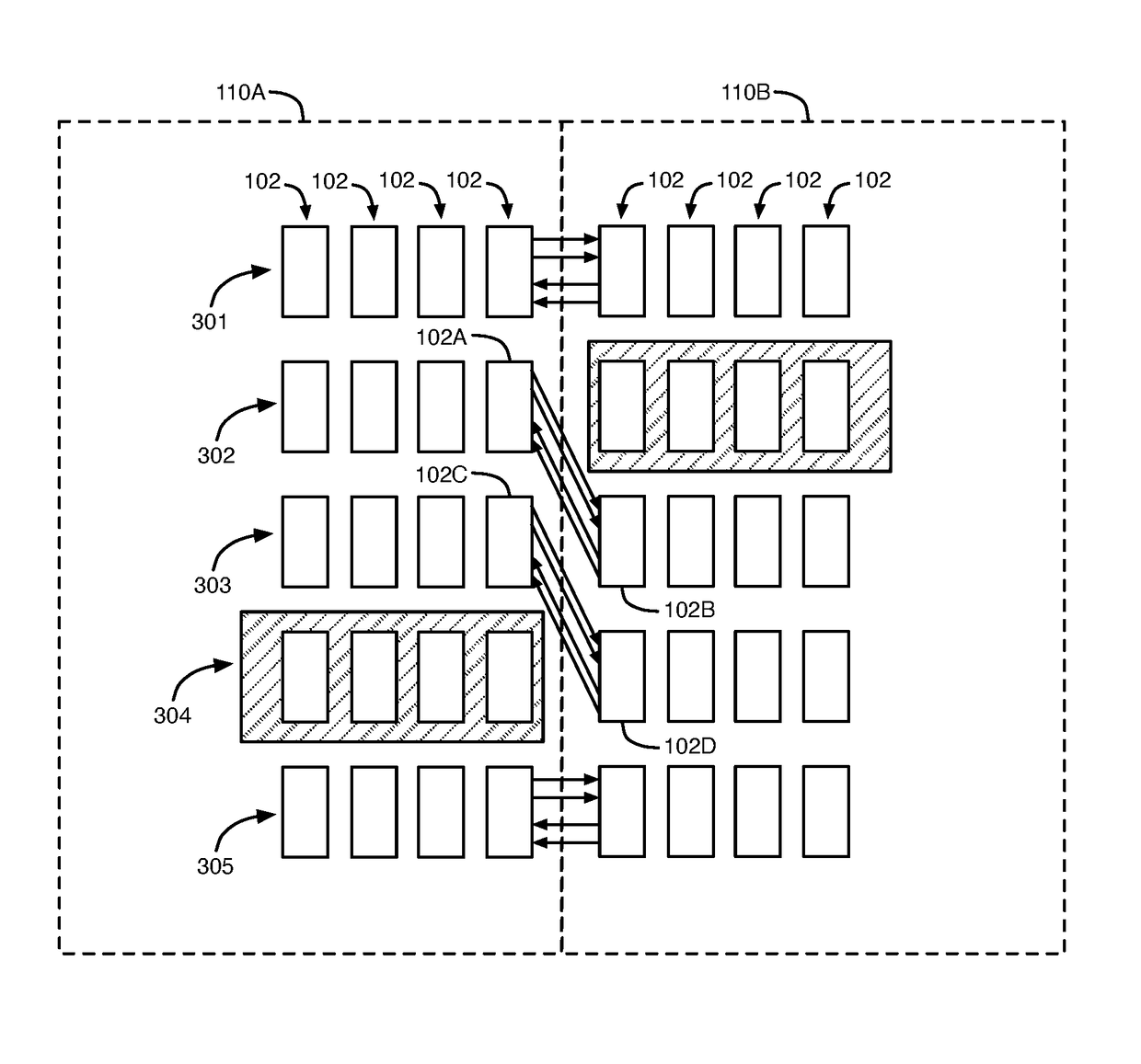
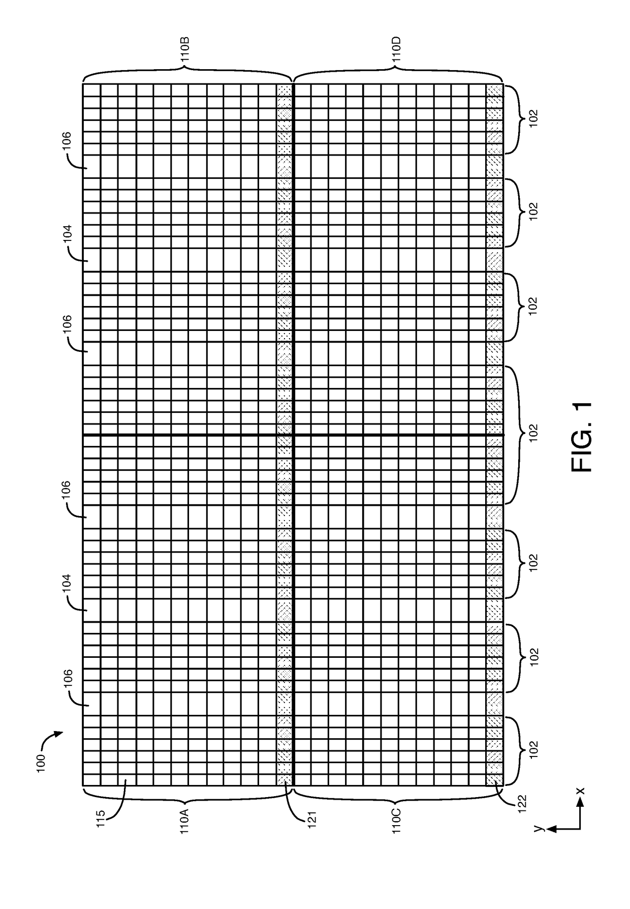
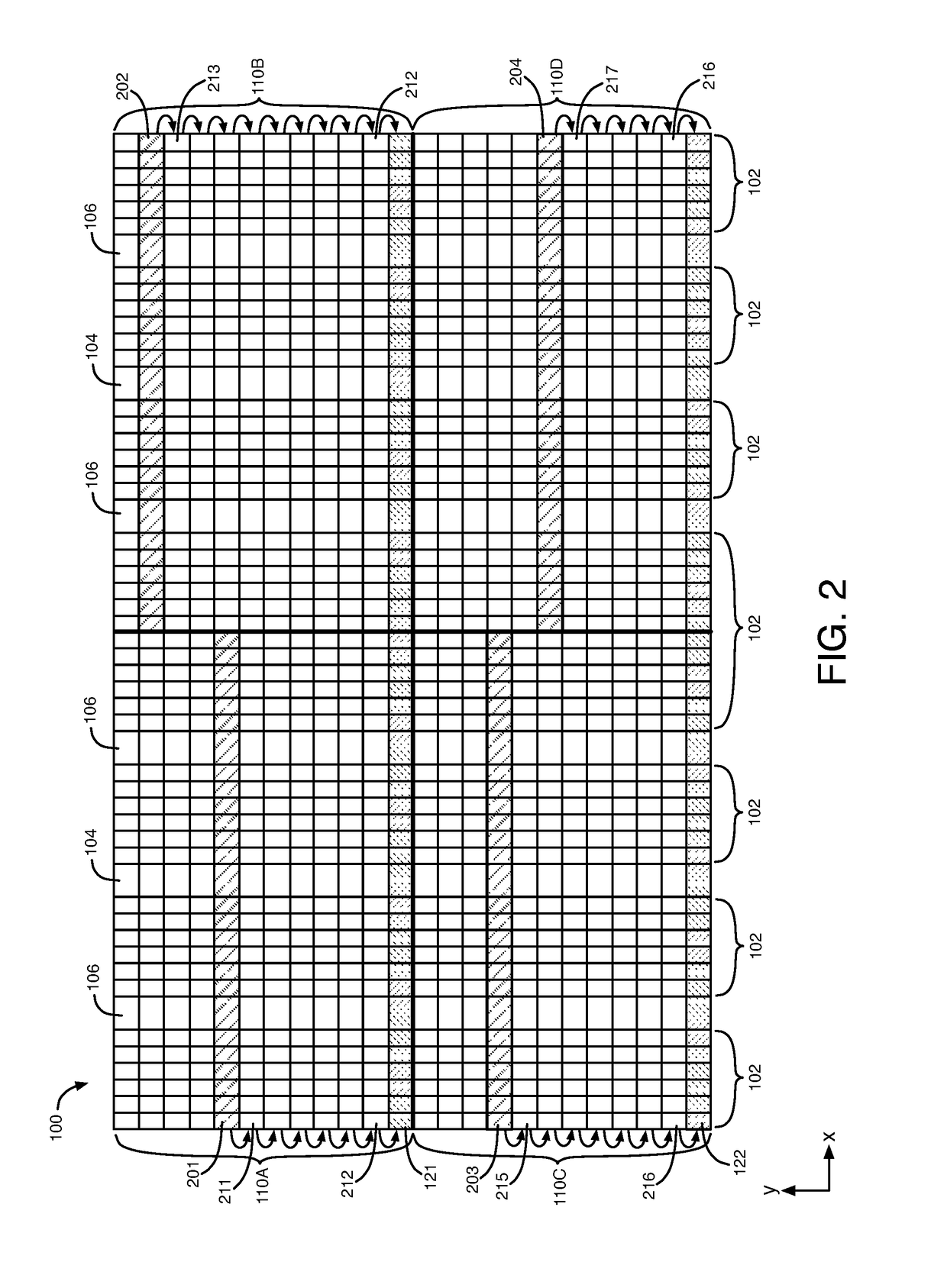
[0015]As discussed above, many programmable logic ICs implement redundancy by using a row based architecture, in which each row contains an identical set of programmable resources. The programmable routing fabric is designed such that connections between rows of programmable logic circuits have duplicate connections, not visible to the user design, that enable shifting. Shifting allows the programming of one row to be shifted down to the row below it, and maintain the exact logical functionality. In response to a defect being detected in a row of programmable logic circuits in a programmable logic IC, the row in which the defect lies is disabled, and all programming for that row and each subsequent row is shifted down by one row, such that a redundant row is now able to be programmed to implement part of a user design for the IC.

[0016]Redundancy has a tradeoff between the number of defects that can be repaired and the cost of the redundant rows, and consequently the die area. In exi...


PUM


Abstract

An integrated circuit includes rows of circuits. A first region of the integrated circuit includes a first portion of each of the rows of circuits, and a second region of the integrated circuit includes a second portion of each of the rows of circuits. The integrated circuit shifts functions for a first subset of the rows of circuits to a second subset of the rows of circuits in the first region based on a first defect in a first one of the rows of circuits in the first region. The integrated circuit shifts functions for a third subset of the rows of circuits to a fourth subset of the rows of circuits in the second region based on a second defect in a second one of the rows of circuits in the second region.

Description

FIELD OF THE DISCLOSURE[0001]The present disclosure relates to electronic circuits, and more particularly, to techniques for bypassing defects in rows of circuits in an integrated circuit.BACKGROUND[0002]Programmable logic integrated circuits (ICs), such as field programmable gate arrays (FPGAs) and programmable logic devices (PLDs), typically include blocks of programmable logic circuits. All integrated circuits are susceptible to manufacturing defects. In order to increase production yields, programmable logic ICs may be provided with spare or redundant circuits. Programmable logic ICs having redundant circuitry can help improve production yields by repairing defective regions on the ICs by engaging the redundant circuitry. A row based redundancy scheme typically provides at least one redundant or “spare” row for several rows of programmable logic circuits and its associated routing. Typically, a repairable region may be above the redundant row such that, if one of the rows of the...

Claims


Application Information

Patent Timeline
Patent Type & Authority Patents(United States)
IPC IPC(8): H03K19/003H03K19/177H03K19/173
CPCH03K19/17764H03K19/00392H03K19/17736G06F11/184G06F15/7867
Inventor LEWIS, DAVID
Owner INTEL CORP
Why Eureka
Try Eureka