Eureka AIR delivers breakthrough ideas for toughest innovation challenges, trusted by R&D personnel around the world.

Abnormality diagnosis system of air-fuel ratio sensor

a technology of air-fuel ratio and abnormal diagnosis system, which is applied in the direction of electric control, combustion engines, machines/engines, etc., can solve the problems that the air-fuel ratio sensor cannot generate a suitable output corresponding to the air-fuel ratio, and the air-fuel ratio cannot be accurately controlled by feedback to the target air-fuel ratio, so as to achieve the effect of reliably detecting a crack in the element of the air-fuel ratio sensor

Active Publication Date: 2018-02-27
TOYOTA JIDOSHA KK
View PDF10 Cites 5 Cited by
  • Summary
  • Abstract
  • Description
  • Claims
  • Application Information

AI Technical Summary

Benefits of technology

[0018]According to the present invention, it is possible to reliably detect a crack of element of an air-fuel ratio sensor.

Problems solved by technology

If an element cracking, the air-fuel ratio sensor can no longer generate a suitable output corresponding to the air-fuel ratio.
As a result, the air-fuel ratio can no longer be accurately controlled by feedback to the target air-fuel ratio.

Method used


Image

  • Abnormality diagnosis system of air-fuel ratio sensor
  • Abnormality diagnosis system of air-fuel ratio sensor
  • Abnormality diagnosis system of air-fuel ratio sensor

Examples


second embodiment

[0128]Next, referring to FIG. 19 to FIG. 22, an abnormality diagnosis system of a second embodiment of the present invention will be explained. The configuration and control of the abnormality diagnosis system of the second embodiment are basically the same as the configuration and control of the abnormality diagnosis system of the first embodiment except for the parts explained below.

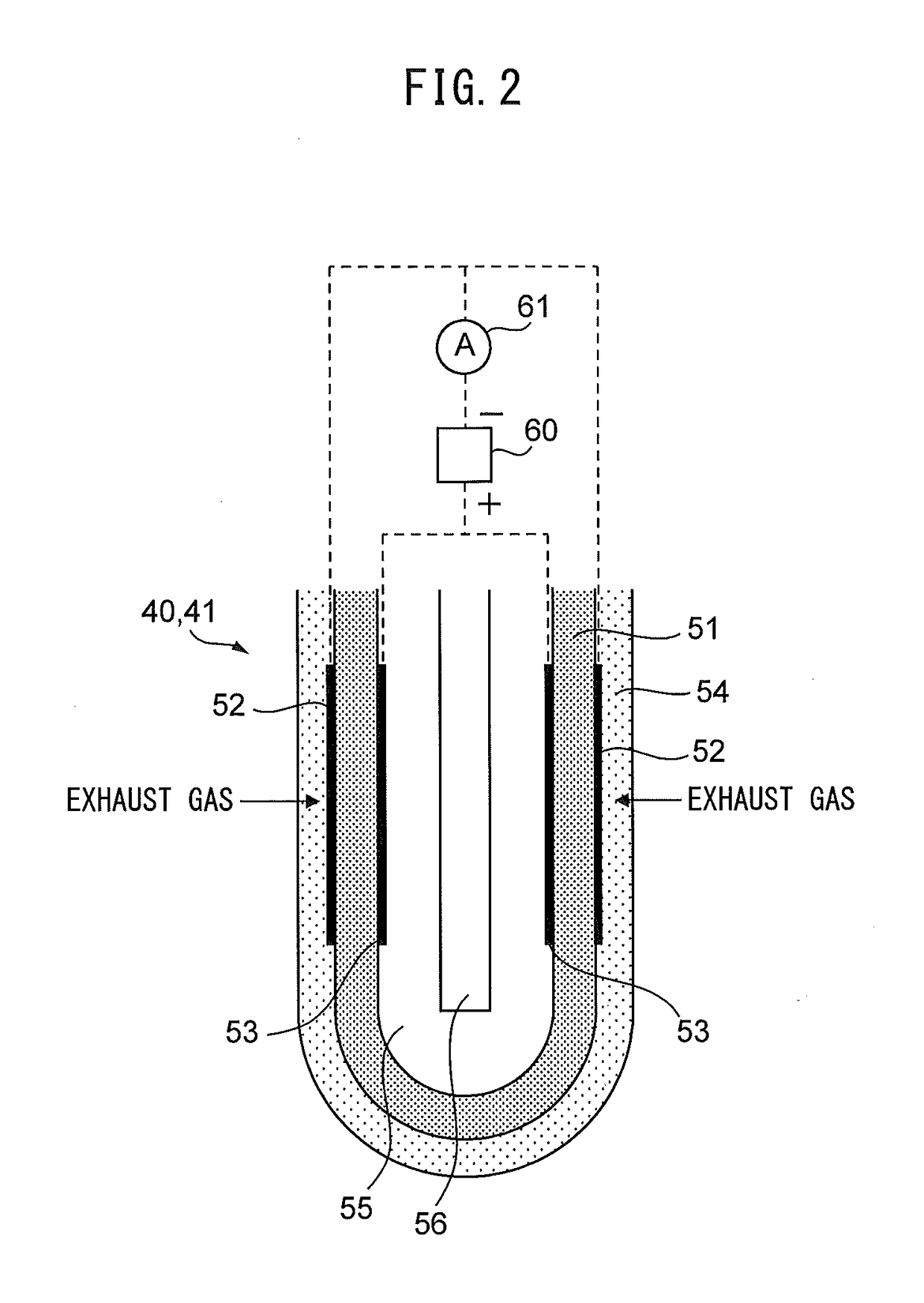
[0129]In this regard, as explained using FIG. 13, when an air-fuel ratio sensor 40 or 41 has a crack of element, if making the temperature of the air-fuel ratio sensor 40 or 41 a high temperature (for example, 700° C.), when the air-fuel ratio of the exhaust gas around the air-fuel ratio sensor 40 or 41 is made a rich air-fuel ratio, the output air-fuel ratio becomes a lean air-fuel ratio with a large lean degree. On the other hand, if the downstream side air-fuel ratio sensor 41 does not have a crack of element, when the air-fuel ratio of the exhaust gas around the air-fuel ratio sensor 40 or 41 is ma...


PUM


Abstract

An abnormality diagnosis system of limit current type air-fuel ratio sensors comprises a current detecting part and a sensor temperature control device. The abnormality diagnosis system uses the current detecting part to detect the output current of the air-fuel ratio sensor when the air-fuel ratio is made the rich air-fuel ratio in the state where temperature of the air-fuel ratio is made the first temperature and when the air-fuel ratio is made the rich air-fuel ratio in the state where the temperature of the air-fuel ratio is made a second temperature higher than the first temperature. It is judged that the air-fuel ratio sensor is abnormal if the output current when the temperature of the air-fuel ratio sensor is the first temperature is larger than the output current when it is the second temperature by a predetermined value or more.

Description

CROSS-REFERENCE TO RELATED APPLICATION[0001]The present application claims priority to Japanese Patent Application No. 2014-216579 filed on Oct. 23, 2014, which is incorporated herein by reference in its entirety.TECHNICAL FIELD[0002]The present invention relates to an abnormality diagnosis system of an air-fuel ratio sensor arranged in an exhaust passage of an internal combustion engine.BACKGROUND ART[0003]In the past, in an internal combustion engine designed to control an air-fuel ratio to a target air-fuel ratio, it is known to arrange a limit current type air-fuel ratio sensor generating a limit current corresponding to the air-fuel ratio in an engine exhaust passage. In such an internal combustion engine, the amount of fuel fed to a combustion chamber is controlled by feedback by the air-fuel ratio sensor so that the air-fuel ratio becomes the target air-fuel ratio. In this regard, in this air-fuel ratio sensor, an element thereof is sometimes cracked, which results in the out...

Claims


Application Information

Patent Timeline
Patent Type & Authority Patents(United States)
IPC IPC(8): F02D41/14F02D41/22
CPCF02D41/1495F02D41/1441F02D41/1494F02D41/222F02D41/1454Y02T10/40
Inventor MIYAMOTO, HIROSHIKIDOKORO, TORUIWAZAKI, YASUSHISUZUKI, KENJIIDE, KOJI
Owner TOYOTA JIDOSHA KK
Why Eureka
Eureka Blog
Learn More