Battery clamp with endoskeleton design

Active Publication Date: 2018-03-20
MIDTRONICS
View PDF981 Cites 37 Cited by
  • Summary
  • Abstract
  • Description
  • Claims
  • Application Information

AI Technical Summary

Problems solved by technology

However, understanding the nature of such storage batteries, how such storage batteries operate and how to accurately test such batteries has been an ongoing endeavor and has proved quite difficult.

Method used


Image

  • Battery clamp with endoskeleton design
  • Battery clamp with endoskeleton design
  • Battery clamp with endoskeleton design

Examples


Embodiment Construction

[0014]Embodiments of the disclosure generally relate to clamps for coupling battery maintenance equipment such as battery chargers, battery testers, etc., to contacts of a storage battery. As will be described in detail further below, in different embodiments, each of the clamps includes an interior skeleton of a first material over-molded with a second material.

[0015]In the discussion below, the term “battery contact” is used to define a portion of the battery onto which clamps of the present disclosure can be applied.

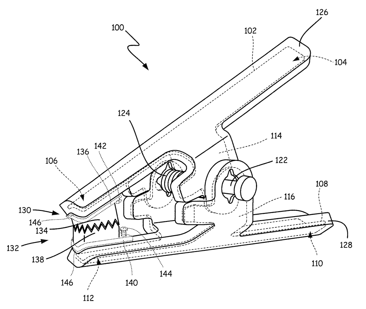
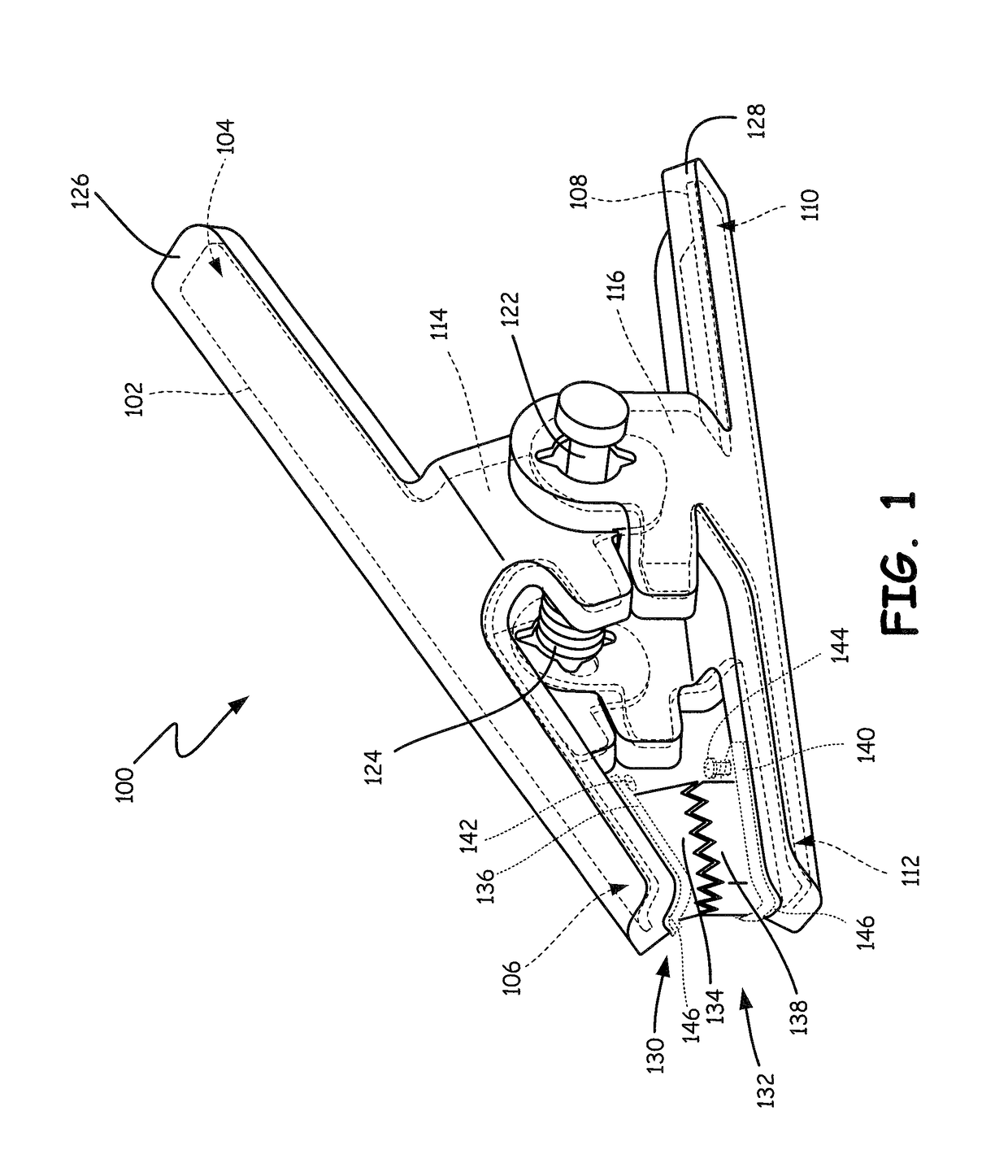
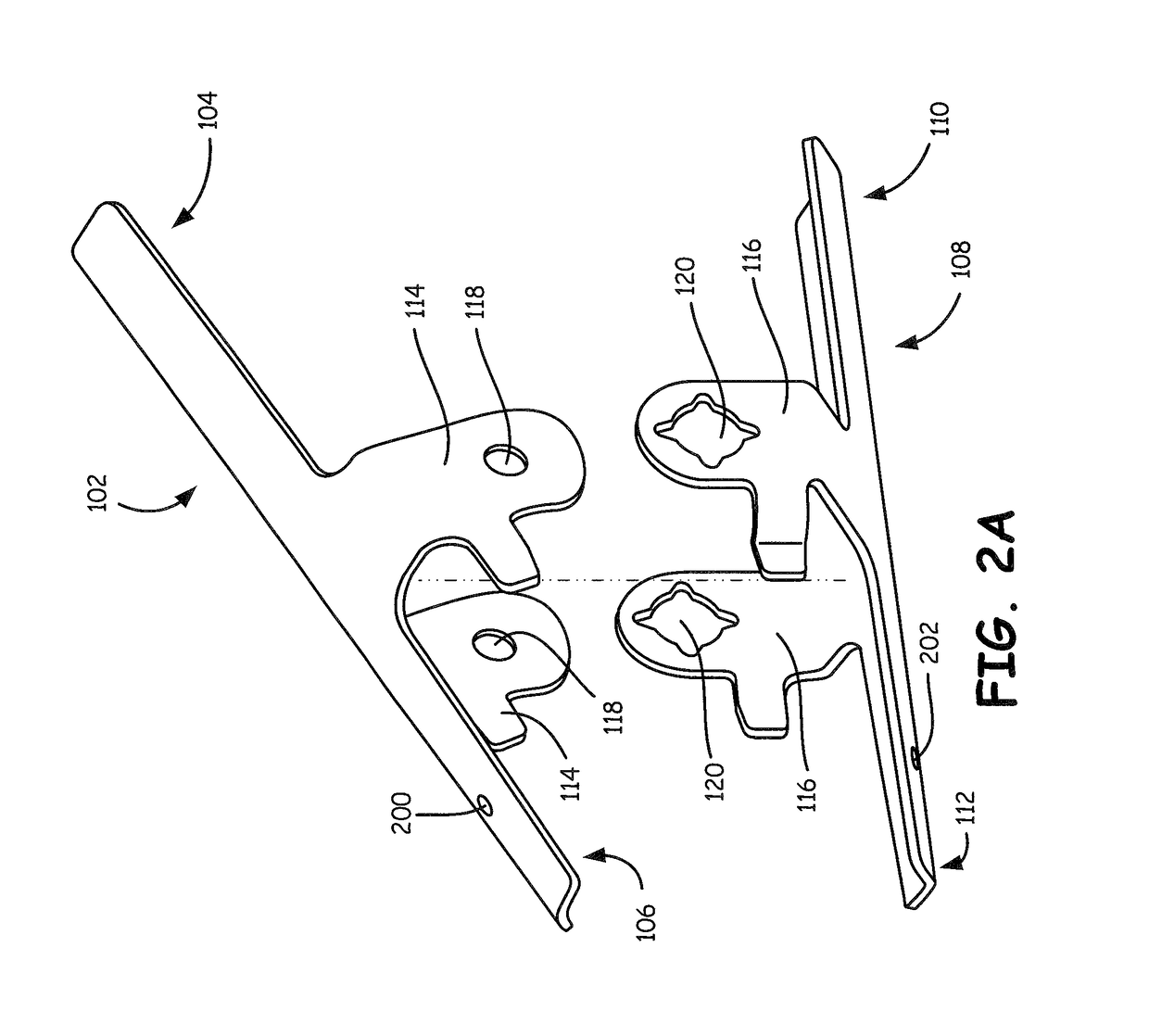
[0016]FIG. 1 is a perspective view showing a Kelvin clamp 100 in accordance with one embodiment. The same reference numerals are used in the various figures to represent the same or similar elements. Kelvin clamp 100 is designed to electrically couple electrical conductors of a Kelvin connection to a battery contact. As will be described below, clamp 100 includes features that render it suitable for use in harsh environments to test and charge lead acid or other batte...


PUM

PropertyMeasurementUnit
voltage potentialaaaaaaaaaa
total voltageaaaaaaaaaa
electricallyaaaaaaaaaa

Abstract

A clamp for coupling an electronic battery tester to a post of a storage battery. The clamp includes a first metal arm that extends from a first proximal end to a first distal end and a second metal arm that extends from a second proximal end to a second distal end. A first hinge portion on the first metal arm is positioned between the first proximal end and the first distal end. A second hinge portion is positioned on the second metal arm between the second proximal end and the second distal end. A pivot is configured to pivotally couple the first hinge portion to the second hinge portion. A first covering is overmolded on the first metal arm and a second covering is overmolded on the second metal arm.

Description

CROSS-REFERENCE TO RELATED APPLICATION[0001]The present application is based on and claims the benefit of U.S. provisional patent application Ser. No. 61 / 928,167, filed Jan. 16, 2014, the content of which is hereby incorporated by reference in its entirety.BACKGROUND[0002]The present embodiments generally relate to storage batteries. More specifically, the present embodiments relate to Kelvin clamps for electrically coupling to storage batteries.[0003]Storage batteries, such as lead acid storage batteries of the type used in the automotive industry, have existed for many years. However, understanding the nature of such storage batteries, how such storage batteries operate and how to accurately test such batteries has been an ongoing endeavor and has proved quite difficult. Storage batteries consist of a plurality of individual storage cells electrically connected in series. Typically, each cell has a voltage potential of about 2.1 volts. By connecting the cells in series, the voltag...

Claims


Application Information

Patent Timeline
Patent Type & Authority Patents(United States)
IPC IPC(8): G01N27/416G01R31/36G01R1/067H01R43/20H01R11/24H01R4/48H01M10/42
CPCH01R11/24G01R1/06711G01R31/3696H01R43/20H01M10/4285Y10T29/4922H01R2201/20Y02E60/10G01R31/364
Inventor BERTNESS, KEVIN I.
Owner MIDTRONICS
Why Eureka
Try Eureka