Fast pulse generator

a generator and fast technology, applied in the direction of pulse generators, electric pulse generators, electrical apparatus, etc., can solve the problems of limiting the rise time of output pulses, affecting the output pulse width, and insertion loss of switches, so as to achieve shortening, saturating very quickly, and effective sharpening of pulse edges

Inactive Publication Date: 2018-04-10
THE UNIV COURT OF THE UNIV OF GLASGOW
View PDF7 Cites 0 Cited by
  • Summary
  • Abstract
  • Description
  • Claims
  • Application Information

AI Technical Summary

Benefits of technology

[0006]Because the frequency multiplier is a non-linear device that only conducts above a threshold and saturates very quickly, an effective sharpening of the pulse edges is provided, which allows for the generation of shorter, and so faster, output pulses.

Problems solved by technology

A disadvantage of this arrangement is that the switch parameters determine the output pulse width.
A further limitation is that when a diode is used, pulse rise times are limited by the intrinsic bandwidth of the switch pulse input, which in turn limits the output pulse rise time.
In addition, the switch has an insertion loss, which reduces the output power.
Also, the output power is restricted by the power handling capability of the switch.
Any attempt to overcome the losses using an amplifier, places restrictions on the amplifier bandwidth, and as frequency increases these restrictions become more difficult to satisfy.

Method used


Image

  • Fast pulse generator
  • Fast pulse generator
  • Fast pulse generator

Examples


Embodiment Construction

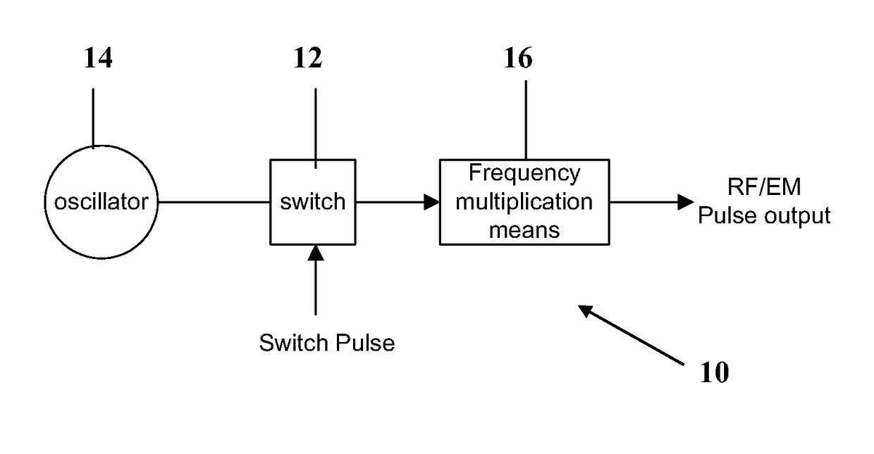
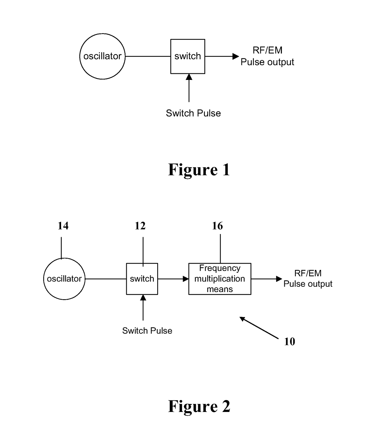
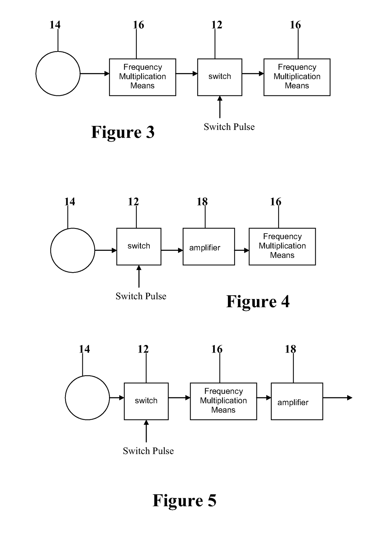
[0019]FIG. 2 shows a pulse generator 10 including a pulsed switch 12 connected between an oscillator 14 and a frequency multiplier 16. Any suitable oscillator 14 could be used, provided it is able to drive the frequency multiplier non-linearly 16. The multiplier 16 may include one or more non-linear devices, for example one or more varactor diodes, FETs, bipolar or other types of diode. Although FIG. 2 shows only a single frequency multiplier 16, there may be a plurality of these, with the pulsed switch 12 connected between adjacent multipliers, as shown in FIG. 3. The pulsed switch 12 may be a semiconductor device or a mixer means, for example, a diode or a four-quadrant multiplier or double balanced mixer or any other relatively fast switch. In any case, the switch 12 may be operable to produce bi-phase pulses. Alternatively, the switch 12 may be operable to produce multi-phasic pulses.

[0020]Because the multiplier 16 of FIGS. 2 and 3 is a nonlinear device that only conducts above ...


PUM


Abstract

A pulse generator is disclosed. The pulse generator can include a pulsed switch, such as a diode. The pulsed switched can be connected between an input source, such as an oscillator and a frequency multiplier.

Description

RELATED APPLICATIONS[0001]This application is a divisional of U.S. patent application Ser. No. 11 / 575696, filed 21 Mar.2007; which claims priority from GB 0421178.5, filed 23 Sep. 2004, both of which are incorporated herein in their entirety.TECHNICAL FIELD[0002]The present invention relates to a fast pulse generator, and in particular a fast radio frequency pulse generator having an output in the frequency range of tens of kilohertz to 100s of gigahertz.BRIEF SUMMARY OF THE INVENTION[0003]FIG. 1 shows a conventional radio frequency switch pulse generator. This has an oscillator that is connected to a pulsed switch, thereby to provide a fast, pulsed output. In practice, the switch is typically a diode. A disadvantage of this arrangement is that the switch parameters determine the output pulse width. A further limitation is that when a diode is used, pulse rise times are limited by the intrinsic bandwidth of the switch pulse input, which in turn limits the output pulse rise time. In ...

Claims


Application Information

Patent Timeline
Patent Type & Authority Patents(United States)
IPC IPC(8): H03K3/00H03B19/00H03B19/16
CPCH03B19/16
Inventor BOLTON, DAVID ROBERTSMITH, GRAHAM
Owner THE UNIV COURT OF THE UNIV OF GLASGOW
Why Eureka
Try Eureka