
Ultrasound catheter having protective feature against breakage

a technology of ultrasound catheter and protective feature, which is applied in the field of medical equipment, can solve problems such as stress exceeding the elastic limit of ultrasound transmission members, and achieve the effect of preventing or minimizing the introduction of debris and improving visibility

Inactive Publication Date: 2018-05-01
FLOWCARDIA
View PDF3 Cites 16 Cited by
  • Summary
  • Abstract
  • Description
  • Claims
  • Application Information

AI Technical Summary

Benefits of technology

The secure attachment of the ultrasound transmission member to the catheter body or guidewire tube minimizes the risk of debris entering the vasculature during procedures, enhancing the safety and efficacy of the ultrasound system by reducing breakage-related complications.

Problems solved by technology

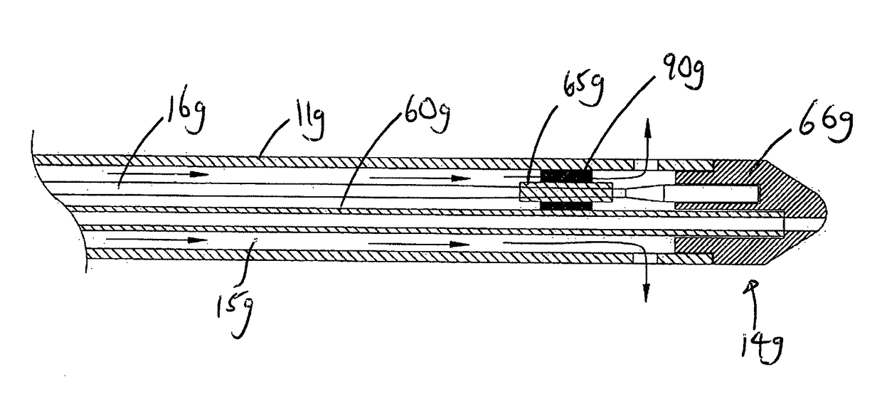
Thus, any external forces applied to the ultrasound transmission member in this region may result in stresses exceeding the elastic limit of the ultrasound transmission member.

Method used


Image

  • Ultrasound catheter having protective feature against breakage
  • Ultrasound catheter having protective feature against breakage
  • Ultrasound catheter having protective feature against breakage

Examples


Embodiment Construction

[0021]The following detailed description is of the best presently contemplated modes of carrying out the invention. This description is not to be taken in a limiting sense, but is made merely for the purpose of illustrating general principles of embodiments of the invention. The scope of the invention is best defined by the appended claims. In certain instances, detailed descriptions of well-known devices, compositions, components, mechanisms and methods are omitted so as to not obscure the description of the present invention with unnecessary detail.

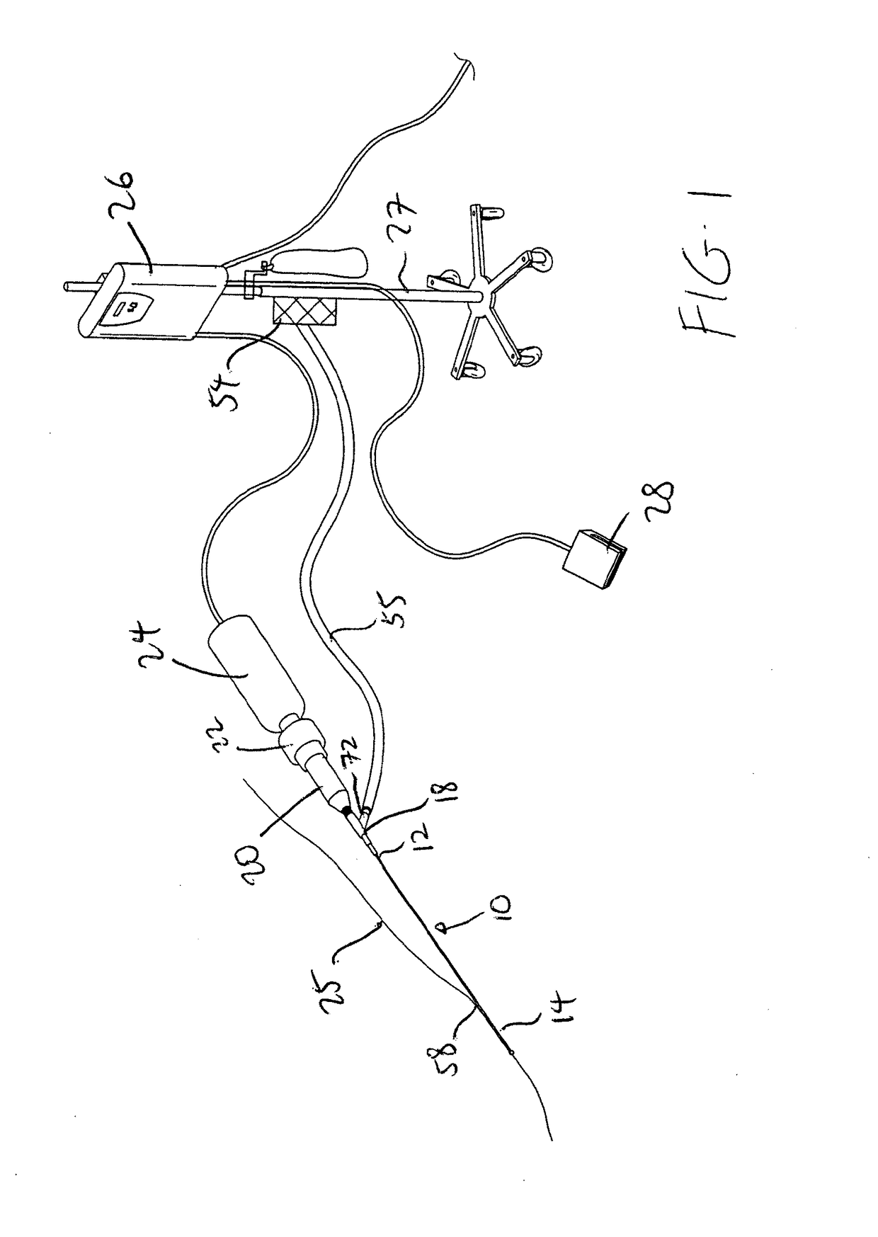
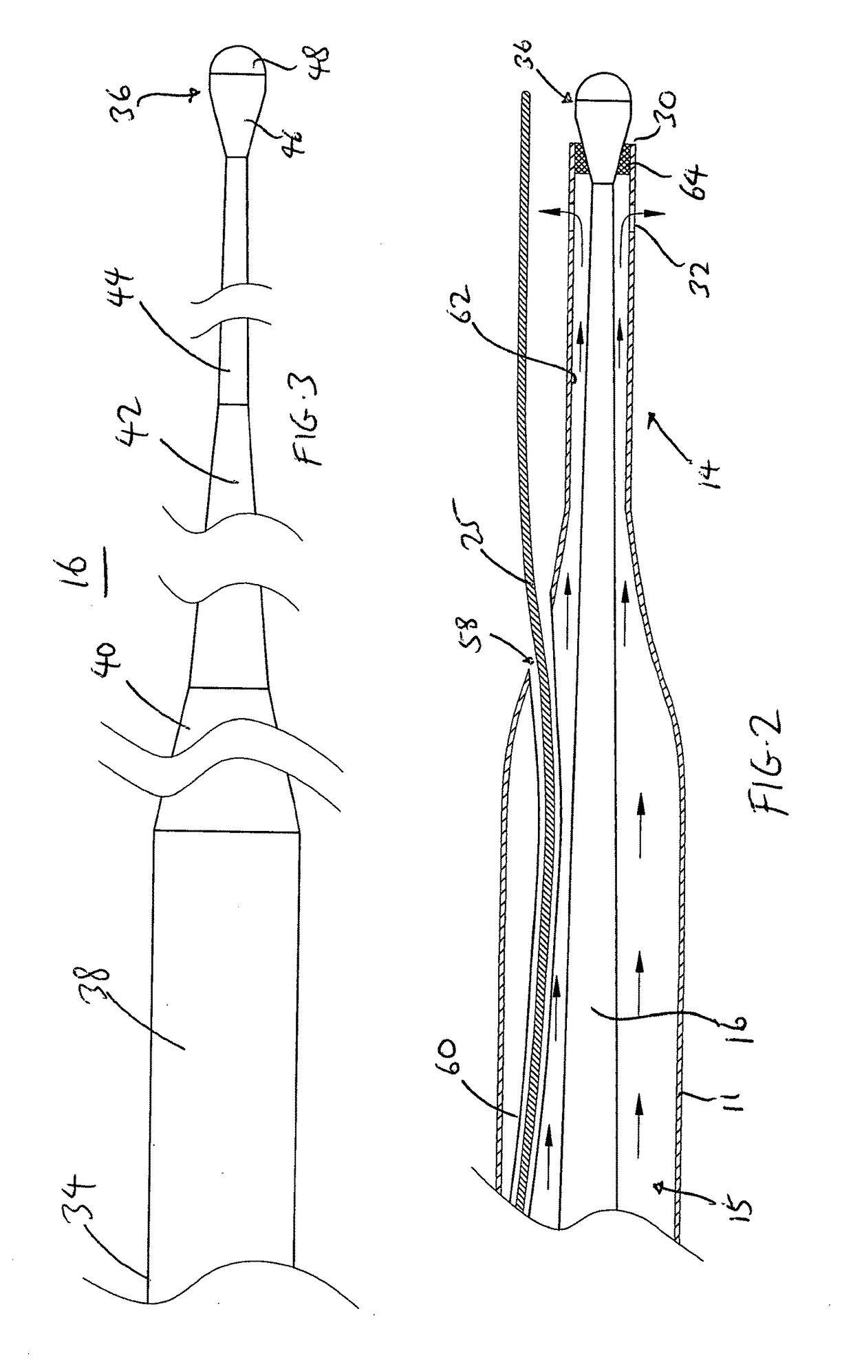
[0022]FIG. 1 illustrates an ultrasound system according to the present invention for use in ablating and removing occlusive material inside the vessel of an animal or human. Referring to FIGS. 1 and 2, the ultrasound system includes an ultrasound catheter device 10 which has an elongate catheter body 11 having a proximal end 12, a distal end 14, and defining at least one lumen 15 extending longitudinally therethrough. The ultrasound cat...


PUM


Abstract

An ultrasound catheter has an elongate flexible catheter body having a lumen extending longitudinally therethrough, and an ultrasound transmission member extending longitudinally through the lumen of the catheter body. The ultrasound transmission member has a proximal end that is coupled to a separate ultrasound generating device, and a distal tip that is attached to the distal end of the ultrasound transmission member and which is located at the distal end of the catheter body. The ultrasound transmission member is directly attached to the catheter body and / or to a guidewire tube either directly or via an attachment device. The catheter has an additional radiopaque marker positioned on the distal end the catheter.

Description

[0001]This application is a continuation-in-part of patent application Ser. No. 12 / 004,984 filed 21 Dec. 2007, issued as U.S. Pat. No. 8,496,669; application Ser. No. 12 / 004,984 is a continuation-in-part of patent application Ser. No. 11 / 594,663 filed 7 Nov. 2006, issued as U.S. Pat. No. 8,133,236 on 13 Mar. 2012; and this application is a continuation-in-part of patent application Ser. No. 11 / 879,170 filed 16 Jul. 2007, issued as U.S. Pat. No. 8,506,519; patent application Ser. No. 11 / 879,170 is a continuation-in-part of abandoned application Ser. No. 11 / 711,970 filed 27 Feb. 2007; application Ser. No. 11 / 711,970 is a continuation of abandoned application Ser. No. 10 / 601,245 filed 20 Jun. 2003; application Ser. No. 10 / 601,245 is a continuation-in-part of patent application Ser. No.10 / 211,418, filed on 2 Aug. 2002, issued as U.S. Pat. No. 6,855,123 on 15 Feb 2005, and is a continuation-in-part of patent application Ser. No. 10 / 251,227 filed on 20 Sep. 2002, issued as U.S. Pat. No. 6...

Claims


Application Information

Patent Timeline
Patent Type & Authority Patents(United States)
IPC IPC(8): A61B17/32A61B17/22A61M25/00A61M25/01A61M25/09A61B90/00
CPCA61B17/320068A61B17/22012A61M25/0068A61M25/0069A61M25/0082A61M2025/09166A61B2017/22038A61B2017/22039A61B2090/3966A61M25/0108A61M2025/0183A61B2017/22014A61B2017/320069
Inventor NITA, HENRY
Owner FLOWCARDIA
Learn More