Integrated safety device for self-propulsion gas systems

a safety device and gas system technology, applied in the direction of functional valve types, vessel construction details, container discharging methods, etc., can solve the problems of unsatisfactory safety, cylinder is completely empty, and undesirable combustive even

Inactive Publication Date: 2018-06-12
WESTPORT FUEL SYST CANADA INC +1
View PDF33 Cites 0 Cited by
  • Summary
  • Abstract
  • Description
  • Claims
  • Application Information

AI Technical Summary

Benefits of technology

[0015]The present safety device also makes it possible to limit the dimensions, the space occupied and the overall structure of the multipurpose valve to which it is associated.
[0024]In addition, the aim of being able to use such device in current multipurpose valves without foregoing one of the two relief devices of the known type is satisfied, without the need to modify the multipurpose valve and with the advantage of limiting the space occupied.
[0026]According to a preferred embodiment, the safety device further comprises a shut-off valve of the flow of fluid, for example manually activated, upstream of the obturator. The shut-off valve is, moreover, preferably positioned in such a way as not to interfere with the passage of gas between the entry aperture and the exit aperture and intercepts the flow in an auxiliary duct between the entry aperture and the exit aperture of the gas into the atmosphere. The arrangement permits total independence of the three devices and by means of such manual shut-off valve it is possible to empty the tank with the immediate release of the gas into the atmosphere or the channeling of the gas through tubes, without the excess flow device cutting in.

Problems solved by technology

This solution has drawbacks as regards safety however.
In fact, if a maintenance technician attempts to empty the cylinder by fully opening the manual shut-off device, the subsequent triggering of the excess flow device blocks the transit of gas leading the technician to believe that the cylinder is completely empty when instead there is still pressurised gas present inside it.
A subsequent removal of the cylinder valve with pressurised fluid still present therein can result in an undesirable combustive event.
This solution is not however sufficient to provide for adequate safety of the system.
The pressure gauge is in fact a cumbersome instrument which may be damaged in the case of impact and being connected, as such, to one of the secondary passages communicating directly with the inside of the tank a leak due to damage of the pressure gauge cannot be stopped by other devices.
In the case of the pressure-sensitive element, such device is susceptible to rupture or otherwise open when the pressure difference between the entry aperture and the exit aperture exceeds a predefined value, so as to permit the flow of the fluid.

Method used


Image

  • Integrated safety device for self-propulsion gas systems
  • Integrated safety device for self-propulsion gas systems
  • Integrated safety device for self-propulsion gas systems

Examples


Embodiment Construction

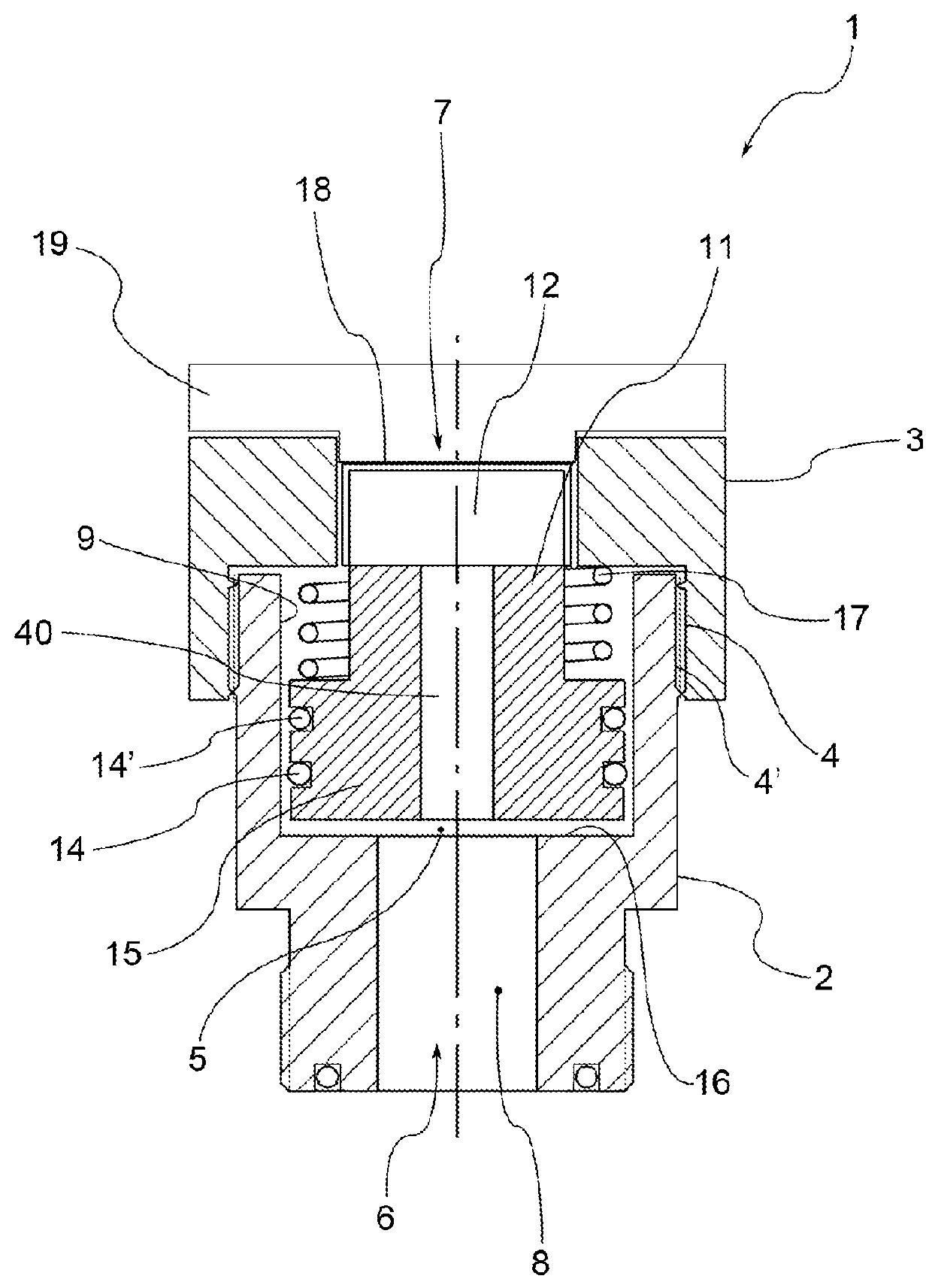
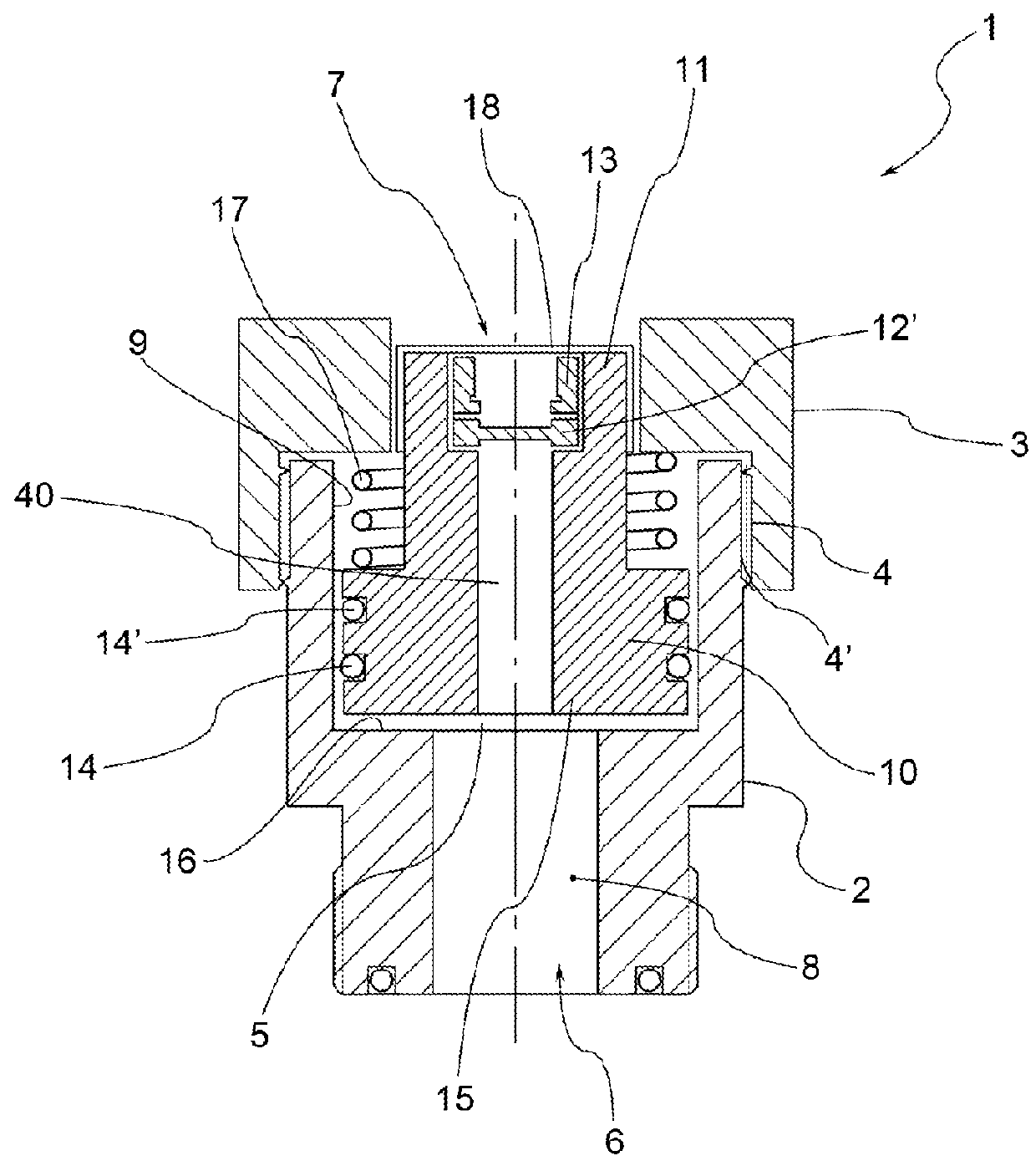
[0040]In the drawings, reference numeral 1 globally denotes a safety device particularly for gas cylinders for self-propulsion systems.

[0041]The safety device 1 can be incorporated in a valve, for example a multipurpose valve for a cylinder containing high pressure gas for a self-propulsion gas system.

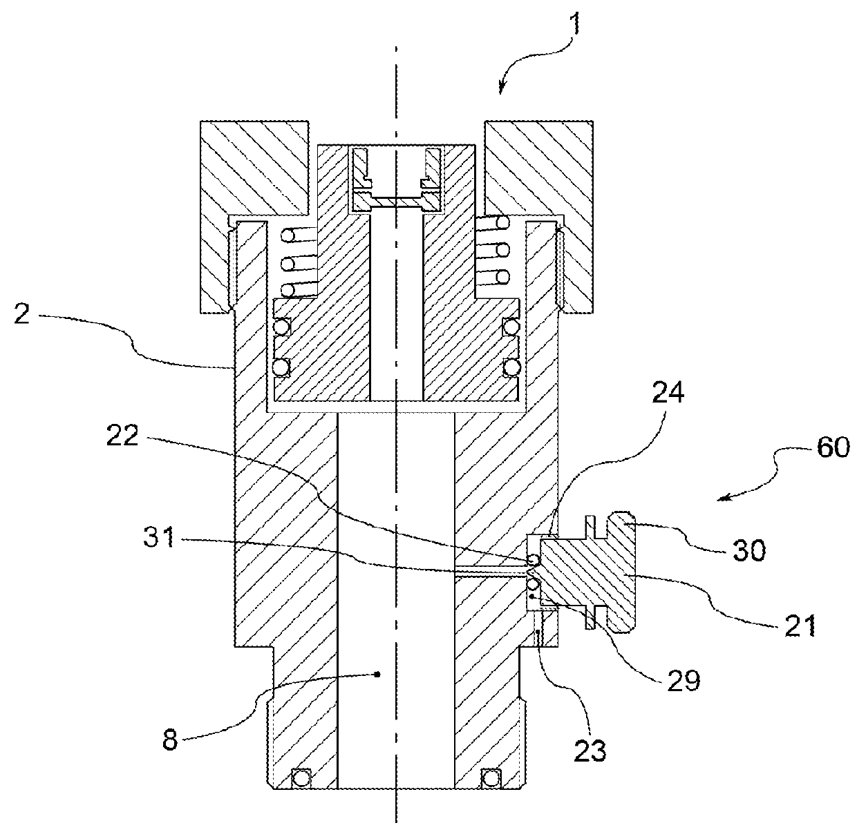
[0042]The safety device 1 comprises a device body which, in one embodiment, is composed of a first portion 2, suitable for being connected to the body of a multipurpose valve or directly to an opening of the cylinder or container, and a second portion 3 associated with first portion 2. Advantageously, the coupling between the two portions of the body occurs by means of respective threaded connection portions 4, 4′. Second portion 3 can therefore be removed from first portion 2 for the assembly and the maintenance of the inner components of the device which will be described below.

[0043]In its totality, the device body defines an inner chamber 5 having, on one side, an entry aperture 6 ...


PUM


Abstract

A safety device for a cylinder holding gaseous fluids under pressure is disclosed. The safety device has a device body in which a passage is defined for a fluid; the passage extends from an entry aperture, suitable for being placed in fluidic communication with a cylinder, to an exit aperture. An obturator air tightly engages the passage, the obturator is movable from a first position, in which it indicates the presence of fluid at a pressure below a first predefined pressure threshold value, inside the cylinder, and a second position, in which it indicates the presence of fluid at a pressure above the first predefined pressure threshold value inside the cylinder. At least one temperature and / or pressure-sensitive relief device is positioned in the obturator in such a way that, upon exceeding a predefined temperature threshold or upon exceeding a second predefined pressure threshold, the relief device opens the passage for the fluid and permits the flow of fluid from the entry aperture towards the exit aperture.

Description

FIELD OF INVENTION[0001]The present invention relates in general to self-propulsion gas systems using compressed natural gas, liquefied petroleum gas or other gaseous combustibles contained under pressure in a cylinder or container, and relates in particular to an integrated safety device for such systems.BACKGROUND OF THE INVENTION[0002]In motor vehicles with engines which can be gas fuelled, the gaseous fuel is loaded and compressed in at least one cylinder or container. Pursuant to some safety regulations of the trade considered here, each gas cylinder on board a vehicle should be fitted with relief devices to discourage an undesirable combustive event if increases in internal pressure and / or temperature beyond a predefined threshold occur.[0003]Each cylinder is fitted with a shut-off valve to stop flow into and out of the cylinder. Various types of cylinder valves are known which integrate several components, these valves are known as multipurpose valves. Generally speaking, suc...

Claims


Application Information

Patent Timeline
Patent Type & Authority Patents(United States)
IPC IPC(8): F16K17/40F16K17/16F16K37/00F16K17/38F17C13/04F16K17/00
CPCF16K17/003F16K17/38F16K17/383F16K17/40F16K17/403F16K37/0008F16K37/0058F17C13/04F16K17/16F17C2270/0168F17C2205/0314F17C2205/0332F17C2205/0382F17C2205/0394F17C2221/033F17C2221/035F17C2223/0123F17C2223/0153F17C2223/033F17C2223/035F17C2223/036F17C2260/021F17C2260/023
Inventor OMESTI, GIULIADEFILIPPI, ROBERTOFARZIN, SOROUSHBRIZZOLARI, GIULIO
Owner WESTPORT FUEL SYST CANADA INC
Why Eureka
Try Eureka